LaserSpeed
Interfacing with the
Analog speed data can be obtained in a
There are two configuration settings that affect the operation of the analog output. The Analog Zero Scale Velocity sets the speed where the analog output reaches 0V. The Analog Full Scale Velocity sets the speed where the analog output reaches 2V. At speeds between these two settings, the analog output increases linearly as the speed increases from the Analog Zero Scale Velocity to the Analog Full Scale Velocity.
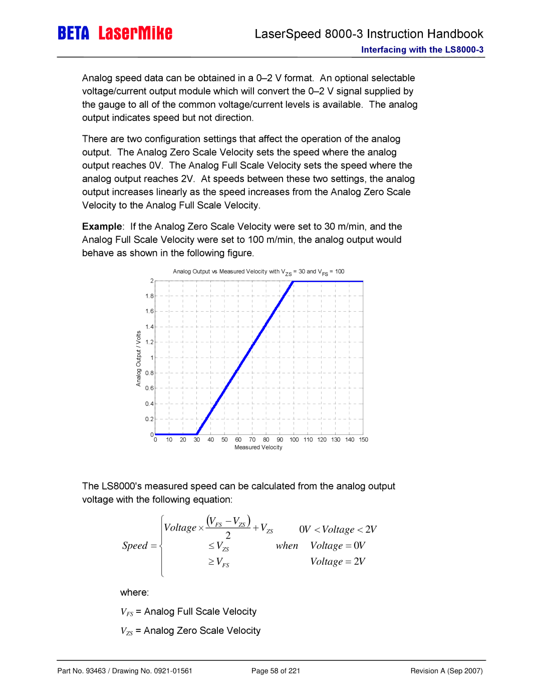
Example: If the Analog Zero Scale Velocity were set to 30 m/min, and the Analog Full Scale Velocity were set to 100 m/min, the analog output would behave as shown in the following figure.
Analog Output / Volts
Analog Output vs Measured Velocity with VZS = 30 and VFS = 100 2 ![]()
1.8
1.6
1.4
1.2
1
0.8
0.6
0.4
0.2
00 | 10 | 20 | 30 | 40 | 50 | 60 | 70 | 80 | 90 | 100 | 110 | 120 | 130 | 140 | 150 |
|
|
|
|
|
| Measured Velocity |
|
|
|
|
|
| |||
The LS8000's measured speed can be calculated from the analog output voltage with the following equation:
⎧Voltage ⋅ | (VFS − VZS ) | + V | 0V | < | Voltage | < | 2V |
| |||||||
⎪ | 2 | ZS |
|
| |||
⎪ |
| when Voltage = 0V |
| ||||
Speed = ⎨ | ≤ VZS |
|
| ||||
⎪ | ≥ VFS |
| Voltage = 2V |
| |||
⎪ |
|
| |||||
⎩ |
|
|
|
|
|
|
|
where:
VFS = Analog Full Scale Velocity
VZS = Analog Zero Scale Velocity
Part No. 93463 / Drawing No. | Page 58 of 221 | Revision A (Sep 2007) |