Manuals
/
Laser
/
Computer Equipment
/
Computer Accessories
Laser
LS8000-3
manual
Part No / Drawing No 190 Revision a Sep
Models:
LS8000-3
1
190
221
221
Download
221 pages
9.92 Kb
187
188
189
190
191
192
193
194
Specs
Install
Chart Recorder Screen
Connector Gender Signals
Default Gateway Address
Connecting Power to the Gauge
Warranty
Dimension
Dual Switch Configuration
Length Reset Input Pin
Page 190
Image 190
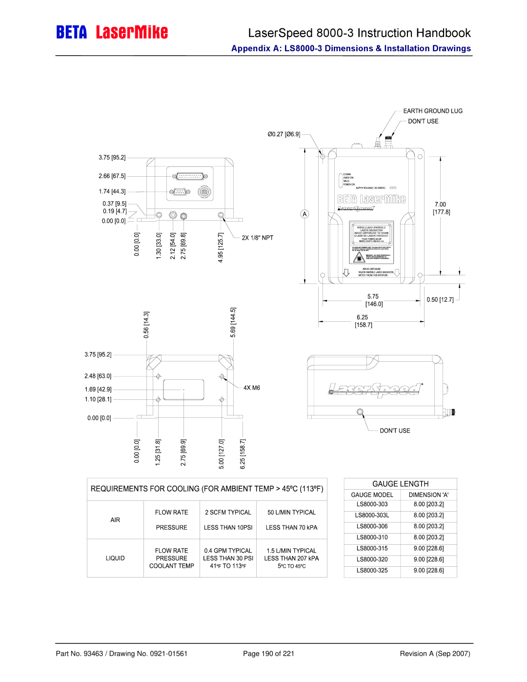
LaserSpeed
8000-3
Instruction Handbook
Appendix A:
LS8000-3
Dimensions & Installation Drawings
Part No. 93463 / Drawing No.
0921-01561
Page 190 of 221
Revision A (Sep 2007)
Page 189
Page 191
Page 190
Image 190
Page 189
Page 191
Contents
LaserSpeed LS8000-3
Declaration of Conformity
Contents
Mounting Dimensions for 85328
Ethernet Communication
RS-232/RS-422 Communication
LaserTrak Software
Appendix C LS8000X Dimensions & Installation Drawings
Appendix a LS8000-3 Dimensions & Installation Drawings
Appendix B LS8000E Dimensions & Installation Drawings
Appendix E Troubleshooting Guide
Proprietary Statement
Limited Warranty
Service
Manufacturer/Distributor
European Commission Requirements
Safety Information
Intended Use
Peak Power 50mW Wavelength 650-810 nm
Laser Classification
Laser Safety Precautions
Labels and Safety Features
LS8000-3 Labels
LS8000-3E Labels LS8000-3X Labels
System Overview
Introduction
Principle of Operation
Material Movement
Mounting the Gauge
Installing the System
Model Standoff Distance Depth of Field
Mounting Distance
Laser Safety
Ambient Temperature
Environmental Conditions
Air Wipe / Quick Change Window
Steam & Mist
Mounting Location
Open Both Ends
Twinner Lines
Near Twinner Near Takeup
Aligning the Gauge
Types of Gauge Misalignment
Wrong
Gauge Orientation
Connecting Power to the Gauge
Connecting to Outputs
LS8000-3 25-Pin Connector Pinout
Pin Description
LS8000-3 9-Pin Connector Pinout
LS8000-3 M12 Connector Pinout
LS8000-3E/LS8000-3X Connector Pinout
LS8000-3 Connector Pin DB37 39-Pin Description
LaserSpeed 8000-3 Instruction Handbook
LS8000-3E/LS8000-3X Breakaway Cable Pinout
Pin Male 39-Pin Female Description
Maximizing Performance
Material Present Dropout Time Selection
Material Present Adjustment
Validation Time Limit Selection
Starting/Ending Length Correction
Connector Gender Signals
LS8000-3 Interface Connectors
LS8000-3 Rear Panel Connectors
Interfacing with the LS8000-3
DB25 Connector
RS-232 Serial Pinouts LS8000-3 to Computer DB9 Connector
RS-232 Transmit and Receive Pins
RS-232 Serial Pinouts LS8000-3 to Computer DB25 Connector
High Speed Pulse Output Pins 3, 5, 7
User Scaleable Pulse Output Pins 15, 4, 6
Differential vs. Single Ended Pulse Outputs
Quadrature Output Phase Relationships
Typical Full Quadrature Pulse Train with Negative Velocity
Quadrature Outputs at Extremely Low Pulse Frequencies
Definitions
Pulse s Pulse m
Optically Isolated Input Schematic
Material Present Input Pin
Material Present Transition Effect Input Mode
Example
External Active Low
Connecting Material Present Switches
Optical Switch Mode LS8000-3 Material Present Mode
External Active High
Dual Switch Configuration
+12-24VDC Power Signal Ground
Signal Grounds Pins 11, 19
Isolation Not Required between Power Supply and I/O
Measurement Direction Input Pin
Laser Interlock Pin
Laser Interlock Input Circuit
Length Reset Input Pin
Shutter Control Pin
User VIN Pin
Index Printer Pulse Output Pins
+24VDC Power Input Pins 24-25 and Power Grounds Pins
DB9 Connector
RS-422 Transmit +/- and Receive +/- Pins
Analog Output Voltage/Ground Pins
Analog Output Specifications
⎧Voltage ⋅
Measurement Synchronization Input Pins
QualityFactor = Voltage ⋅15
M12 Ethernet Connector
LS8000-3 M12 Connector Pinout
Ethernet Cables
LS8000-3 Interface Cables
DB25 Cables
Part Number Length Cable Description
Heavy Industrial Cables
Breakaway Cables
LaserSpeed 8000-3 Instruction Handbook
Breakaway Cable Mounting Bracket
LS8000-3 Breakout Assemblies
Model Description Compatible With Base Size
Part Interface/Feature Number
Mounting Dimensions for 85328
DB25 Breakout Assemblies
Part Interface/Feature2
Mounting Dimensions for 85321, 85322, 85323
DB37 Breakout Assemblies
RS-422 Connector
Breakout Assembly Pinouts
RS-232 Connector
Pin Description DB25/DB37 Pin
Ethernet Connector
Breakout Assembly A/C Power Connector
Light Stack Interface
Setting Value Command
Application Interfaces
#9CR
Light Stack Laser Meaning Radiation Lamp Emitted?
Yes
Output How To Configure Output Pin Voltage Level
Thermostat Interface
Index Pulse & Length Thresholds
Gauge-Gauge Synchronization
LaserSpeed 8000-3 Instruction Handbook
Single through beam
Banner D10 Through Beam Switch
Signal D10 LaserSpeed
Dual through beam uses two D10 modules
Banner Retroflective Switch Picodot
Signal PD45 LaserSpeed
Signal
DataPro
Configure the LaserSpeed pulse per unit length
DataPro 5000 BB
DataPro 5000 DN
Signal KL5111-A LaserSpeed
Signal KL5101-A LaserSpeed
DataPro 5000 DN Beckhoff I/O
Signal Domino A200 LaserSpeed
Domino a Series
Signal Durant LaserSpeed
Durant President Series
Durant Settings Func # Value
Signal Hengstler LaserSpeed
Hengstler
Signal Imaje S4/S8 LaserSpeed
Imaje S4/S8
Signal MI800
MI800
Signal Newport LaserSpeed
Newport P6000A
Red Lion Paxi
Signal 450-1 LaserSpeed
Siemens Counter Module
Signal Siemens LaserSpeed
Siemens Counter Module 6ES5 385-8MB11
Signal TrueMeter LaserSpeed
TrueMeter
LaserTrak Software
LaserTrak for Windows Installing the LaserTrak Software
System Requirements
Software Installation Procedure
Starting LaserTrak
LaserSpeed 8000-3 Instruction Handbook
LaserSpeed 8000-3 Instruction Handbook
Chart Recorder Screen
Gauge Info
Gauge Status
LaserTrak Menus
LaserTrak Toolbar
File Menu
Tools Menu
Part No / Drawing No 103 Revision a Sep
Terminal Assist Screen
Part No / Drawing No 105 Revision a Sep
LaserTrak Configuration Screens
Part No / Drawing No 107 Revision a Sep
Part No / Drawing No 108 Revision a Sep
Standard Operating Parameters
Output Configuration Parameters
Length Threshold a
Direction Inversion Switch
Advanced Operating Parameters
Length Threshold B
Length Reset Input
Velocity Hold Timeout
Length Reset Value
QF Warning Timeout
Comm LED Control
Chart Recorder Toolbar
Chart Display
Displaying Data
Part No / Drawing No 116 Revision a Sep
Monitor Display
Length Mode Display
Part No / Drawing No 119 Revision a Sep
Part No / Drawing No 120 Revision a Sep
RS-232/RS-422 Communication
Serial Commands to set Baud Rate & Framing
Configuration Setting Serial Command
Baud Rate & Framing
RS-232 Maximum Cable Lengths
Baud Rate & Framing Settings
Setting Baud Rate Framing
RS-232 Baud Recommended Maximum Rate Cable Length
Number of Comm Baud Rate LED Blinks
Baud Rate Indication on Power Up
Valid LED Framing
Automatic Baud Rate Detection
Method
Communication Protocol
Notation Description
Text Example Font Descriptive Text High Speed Pulse Setting
@CR Read
Communication Protocol Command Descriptions
Setting Baud Rate Framing
@NCR Set
RS-232 Baud Rate & Framing
Jncr
Quality Factor Warning Threshold
Quality Factor Warning Timeout
Direction Inversion Switch
Value Line Direction
Hold Velocity If Above
Hold Velocity Timeout
Example
Calibration Trim
Analog Full Scale Velocity
Analog Zero Scale Velocity
Filter Range Enables
Material Present Input Mode
Value Description
Material Present Validation Time
Material Present Dropout Time
Material Present Threshold Level
Hour Meter Current Value
Current & Max Temperature
Velocity at Loss of Material
Tpcr Read
Rate Command
User Update Rate
Averaging Time
RCR or
R0CR
Mode
Length Reset Input Action
Length Reset Value
$RCR Read
UCR Read
Measurement Units
$R4000CR
Uncr Set
Walking Threshold
Minimum Final Length
Material Present Output
Index Pulse Output Function
Value Index Pulse Output Function
Valid Measurement Output
Laser On
QF Warning Output
Shutter Open
Thermostat Output
YCR Read
Index Pulse OPR Setting
Index OPR Pulse Length
Yncr Set
Length Threshold a
Length Threshold B
Pulse Output Function
High Speed Pulse Output Configuration
High Speed Pulse Rate
Sync Output
$LCR Read
User Scaleable Pulse Output Configuration
$LNCR Set
Light Stack Red
Light Stack Yellow
Length Threshold B
User Scaleable Pulse Rate
Pncr
RS-232/RS-422 Traffic
COM LED Function
Value COM LED
Ethernet Status/Traffic LED Status Meaning
Setting Lock
Setting Lock Enabled
Gauge Model and Serial Number
Ethernet Enabled
Ethernet Hardware ID
DHCP=NCR Set
Dhcp Enable/Disable
DHCP?CR Read
Value Effect IP Address
Hostname
IP Address
Command *IPDEFGW?CR Response *IPDEFGW=192.168.0.213CR
Default Gateway Address
Command *IPDEFGW=192.168.0.213CR
Response *IPADDR=192.168.0.213CR
Final Length Mode
Netmask
Format Description Examples
Text Output Mode
Format
Bit Status Field Convention
Read One Line of Measurement Data
Binary Output Mode
Example TE Data Output
Data Processing Procedure
Byte Value
Value Format
Configurable Text Output Mode
Ttncr Set
Notation Description Length Bytes
Read One Line of TT Data
Stop Real-time Output
AUTO232?CR Read
RS-232 Power-On Data Transmission Mode
AUTO232=SCR Set
AUTO422?CR Read
RS-422 Power-On Data Transmission Mode
AUTO422=SCR Set
AUTOUDP?CR Read
UDP Power-On Data Transmission Mode
AUTOUDP=SCR Set
UDP Power-On Data Destination IP Address
UDP Power-On Data Destination Port
Transmission Time Fastest Update Rate
Real-Time Data Timing
Communication Protocol Command List
Setting Lock
High Speed Pulse Output Configuration
User Scaleable Pulse Output Configuration
Setting Lock Enabled
Ethernet Communication
Configuration Settings
Configuration Setting Command Read/Write
Supported Protocols
IP Address Configuration
Dhcp
Ping Example using Dhcp
Start Run Type cmd At the command prompt, type Click OK
Manually Configured IP Address
Telnet Example using Dhcp
Part No / Drawing No 171 Revision a Sep
Ping / Icmp
Ping Example using Manual IP Address
Start Run Type cmd and click OK At the command prompt, type
Or use the IP Address you assigned
TCP Communications
UDP Communications
UDP Command Example
UDP Real-Time Measurement Example
Discovery Beacon Format
UDP Discovery Beacon
Byte Description
Discovery Beacon Response Format
Identifier Value Response Length Bytes
UDP Discovery Beacon Example
Transmitted Discovery Beacon
Received Discovery Beacon Responses
Value 1 IP Address
Value 2 Ethernet Hardware ID Value 3 Dhcp Enabled/Disabled
Value 4 Gauge Model Value 5 Serial Number
Value 6 Host Name
Specifications
General Specifications
Air Cooling
LS8000-3 Specifications
Water Cooling
LS8000-3E Specifications
Air Purge
LS8000-3X Specifications
Gauge Size 508 X 327 X 186 mm 20 X 12.9 X 7.3 Gauge Weight
LS8000-3 Features
Appendix a LS8000-3 Dimensions & Installation Drawings
Part No / Drawing No 190 Revision a Sep
Air Wipe / Quick Change Window optional
Appendix B LS8000E Dimensions & Installation Drawings
Part No / Drawing No 193 Revision a Sep
Part No / Drawing No 194 Revision a Sep
Part No / Drawing No 195 Revision a Sep
Part No / Drawing No 196 Revision a Sep
LS8000-E with AIR Purge see Table
Appendix C LS8000X Dimensions & Installation Drawings
Part No / Drawing No 199 Revision a Sep
Part No / Drawing No 200 Revision a Sep
Part No / Drawing No 201 Revision a Sep
Appendix D Supply Voltage Requirements
Voltage Drop using Single Supply/Single Return
Wire Size Voltage Drop per Foot Voltage Drop per Meter
Dual Conductor Supply
Quad Conductor Supply
Cable Description Power Wires
LaserSpeed Cables
Appendix E Troubleshooting Guide
Communications
See the Automatic Baud Rate Detection
LOCKEN=1CR
Zcrlf
Quality Factor/Valid Measurements
Result of Laser beam inspection
LaserSpeed 8000-3 Instruction Handbook
LaserSpeed 8000-3 Instruction Handbook
Aluminium strip
LS9000 Only
LOCKED=0CR
$N-999999999CR $X999999999CR
Measurements
Environmental conditions
LaserSpeed 8000-3 Instruction Handbook
Miscellaneous
Ethernet
Ethernet option
Index
LaserSpeed 8000-3 Instruction Handbook
Top
Page
Image
Contents