Laser LS8000-3 manual Connecting Power to the Gauge

Models: LS8000-3

1 221
Download 221 pages 9.92 Kb
Page 24
Image 24

LaserSpeed 8000-3 Instruction Handbook

Installing the System

Connecting Power to the Gauge

The gauge requires a 20–28 VDC (nominal 24 VDC) supply to be connected to Pin 24 and/or Pin 25 with the corresponding ground to Pin 12 and/or Pin 13 of the 25-pin D-sub connector. The supply should be able to drive at least 2 Amps. For detailed information on supplying power to the gauge, see Appendix D.

Notes: Do not attach wires to the gauge while power is applied. Make all wiring connections with power turned off. The gauge contains internal fusing (3A, 125 V) on the 24 VDC supply line. This fuse is not user serviceable.

The LS8000-3 is classified as a kit, according to CDRH regulations. It is your responsibility to install a key switch to control the operation of the device. The key switch should be installed as shown in the following figure. It is in line with the 24-volt supply line that will service to power the device. The recommended key switch can be found in the accessory kit. The key switch should be mounted in a convenient location that does not require exposure to the laser beams. After installation, label the panel as to which position corresponds to “Laser On” and “Laser Off.”

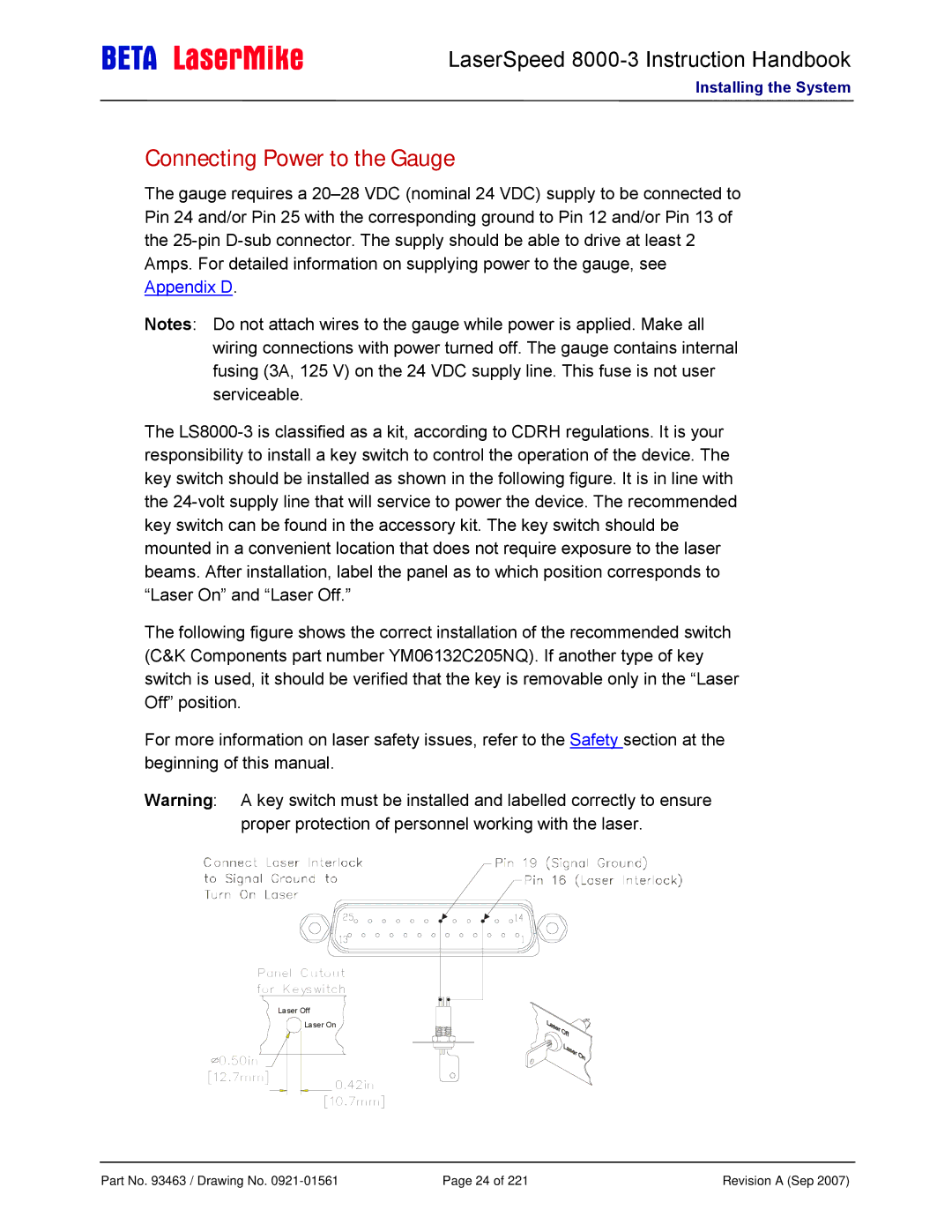
The following figure shows the correct installation of the recommended switch (C&K Components part number YM06132C205NQ). If another type of key switch is used, it should be verified that the key is removable only in the “Laser Off” position.

For more information on laser safety issues, refer to the Safety section at the beginning of this manual.

Warning: A key switch must be installed and labelled correctly to ensure proper protection of personnel working with the laser.

Panel Cutout for Keyswitch

Laser Off

Laser On

0.50in

[12.7mm]

0.42in

[10.7mm]

Part No. 93463 / Drawing No. 0921-01561

Page 24 of 221

Revision A (Sep 2007)

Page 24
Image 24
Laser LS8000-3 manual Connecting Power to the Gauge