|
| LaserSpeed | |
|
| LaserTrak Software | |
|
|
| |
| m/min x 1min/60sec x 10,000 pulses/m = 166,667 1/s ). The range is 0.001 to |
| |
| 100,000. |
|
|
|
|
| |
Measurement Units | Sets the units that the length and speed will be measured in. Available choices |
| |
| are: |
|
|
| • | Feet/sec |
|
| • | Feet/minute |
|
| • | Meters/sec |
|
| • | Meters/min |
|
| • | Inches/min |
|
| • | Millimeters/min |
|
| • | Millimeters/sec |
|
| • | Yards/min |
|
| • | Yards/sec |
|
| Length will be in m, feet, mm, in or yards, depending on the selected value. |
| |
|
|
| |
User Update Rate | The core period determines how often the LaserSpeed sensors provide the |
| |
| LaserTrak software with an updated speed and length measurement. Available |
| |
| choices are Fast (4ms), Medium (32ms) and Slow (100ms) in the Standard |
| |
| settings. For the advanced settings the available choices are 1 to 2000 ms in |
| |
| 1 ms increments. |
| |
| The Recommended User Update Rate is 32 ms. |
| |
|
|
|
|
Output Configuration Parameters
Analog Zero Scale | Sets the speed equal to the analog zero scale. See the Analog Output Voltage |
| Section for details. |
|
|
Analog Full Scale | Sets the speed equal to the analog full scale. See the Analog Output Voltage |
| section for details. |
|
|
AFS Represents QF | When checked the gauge will output QF on the analog output as a 0 to 1 volt |
| signal. 0 - QF 0 and 1 volt |
| speed on the analog output as a 0 to 2 volt signal |
|
|
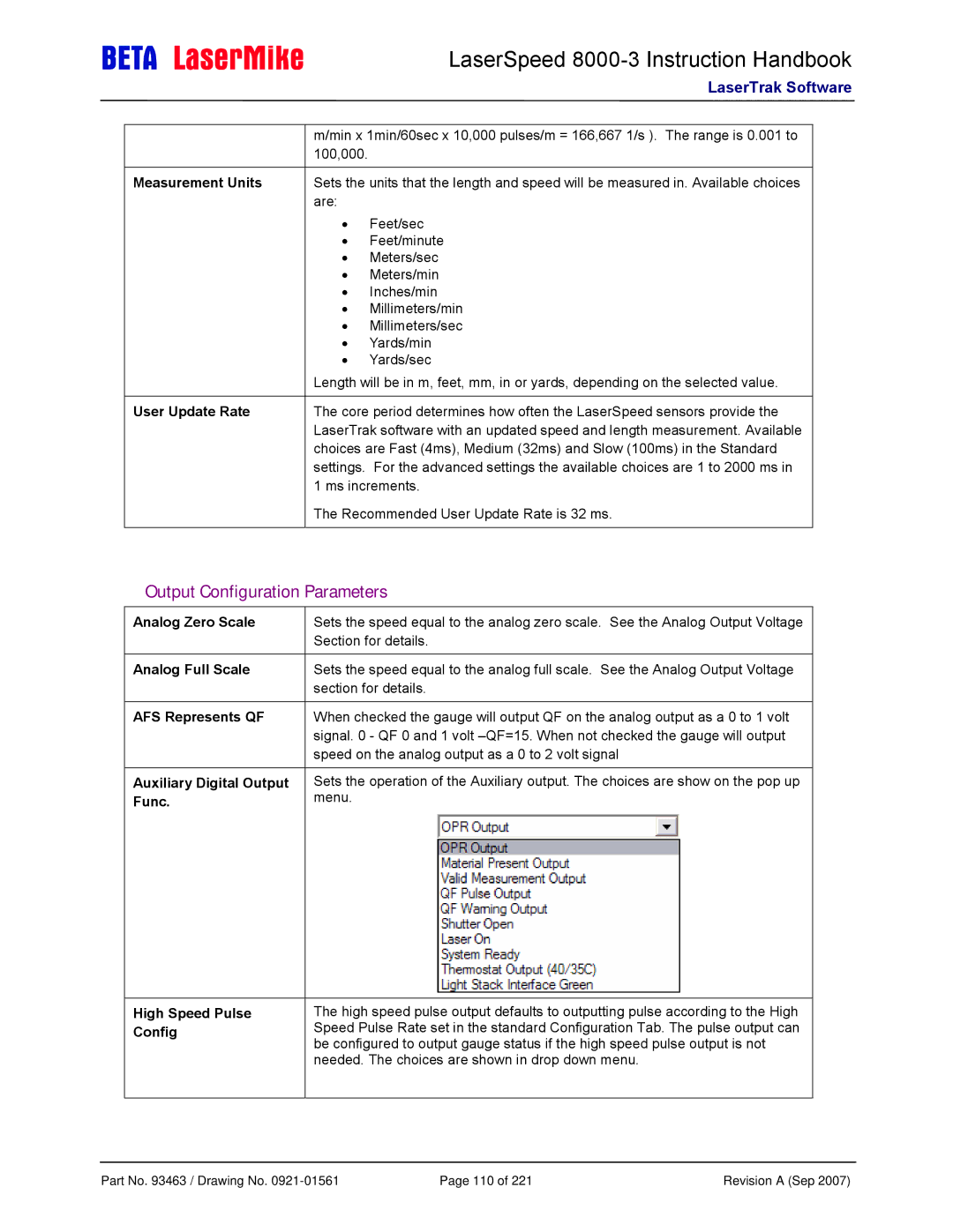
Auxiliary Digital Output | Sets the operation of the Auxiliary output. The choices are show on the pop up |
Func. | menu. |
High Speed Pulse Config
The high speed pulse output defaults to outputting pulse according to the High Speed Pulse Rate set in the standard Configuration Tab. The pulse output can be configured to output gauge status if the high speed pulse output is not needed. The choices are shown in drop down menu.
Part No. 93463 / Drawing No. | Page 110 of 221 | Revision A (Sep 2007) |
