LaserSpeed
Interfacing with the
Index (Printer) Pulse Output (Pins 22-23)
Also referred to as a
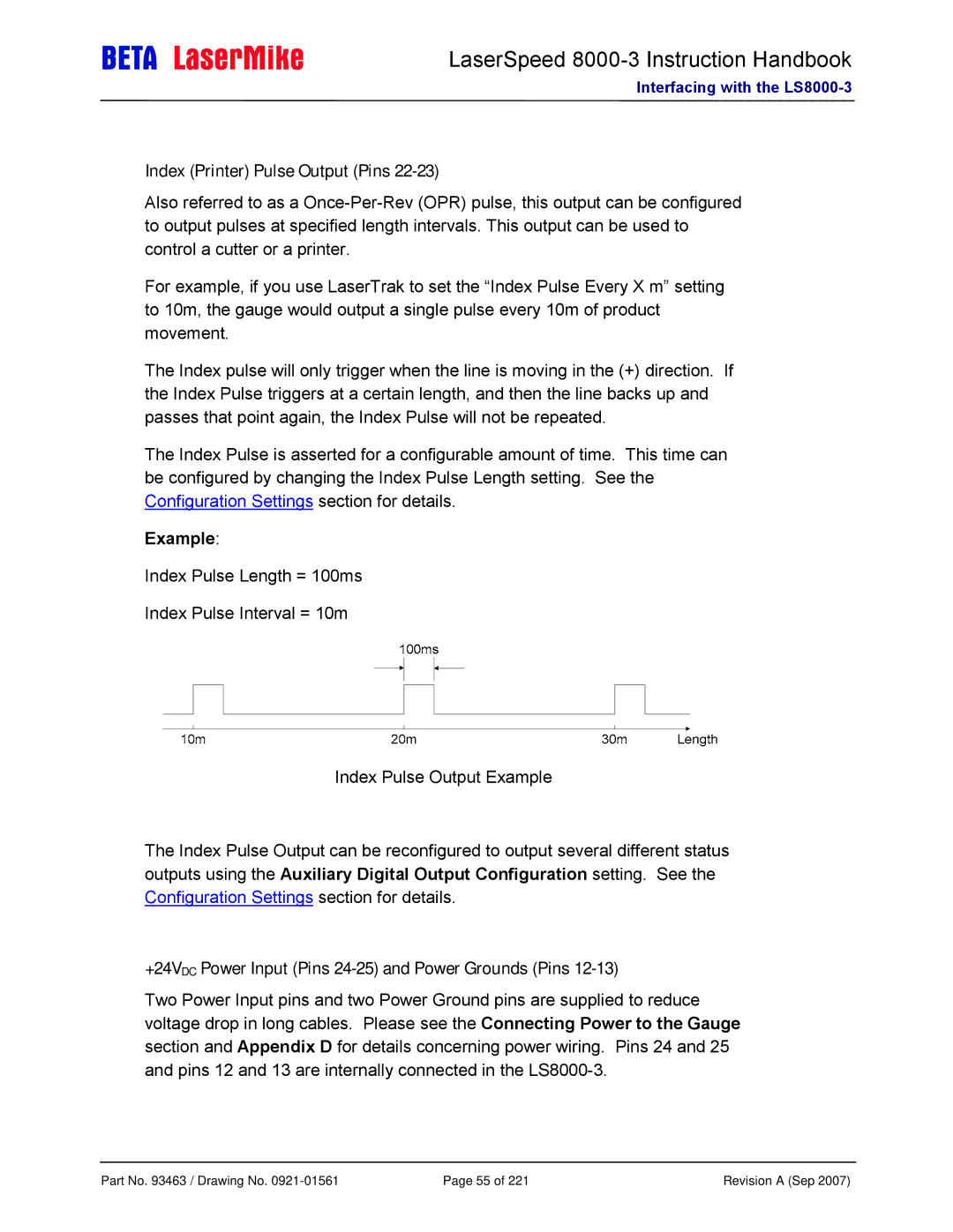
For example, if you use LaserTrak to set the “Index Pulse Every X m” setting to 10m, the gauge would output a single pulse every 10m of product movement.
The Index pulse will only trigger when the line is moving in the (+) direction. If the Index Pulse triggers at a certain length, and then the line backs up and passes that point again, the Index Pulse will not be repeated.
The Index Pulse is asserted for a configurable amount of time. This time can be configured by changing the Index Pulse Length setting. See the Configuration Settings section for details.
Example:
Index Pulse Length = 100ms
Index Pulse Interval = 10m
Index Pulse Output Example
The Index Pulse Output can be reconfigured to output several different status outputs using the Auxiliary Digital Output Configuration setting. See the Configuration Settings section for details.
+24VDC Power Input (Pins 24-25) and Power Grounds (Pins 12-13)
Two Power Input pins and two Power Ground pins are supplied to reduce voltage drop in long cables. Please see the Connecting Power to the Gauge section and Appendix D for details concerning power wiring. Pins 24 and 25 and pins 12 and 13 are internally connected in the
Part No. 93463 / Drawing No. | Page 55 of 221 | Revision A (Sep 2007) |
