| LaserSpeed | |
| LaserTrak Software | |
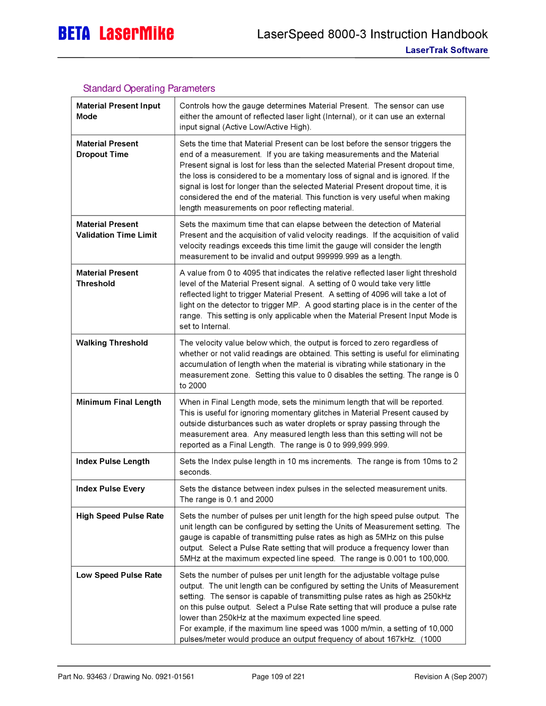
Standard Operating Parameters | ||
|
|
|
Material Present Input | Controls how the gauge determines Material Present. The sensor can use |
|
Mode | either the amount of reflected laser light (Internal), or it can use an external |
|
| input signal (Active Low/Active High). |
|
|
|
|
Material Present | Sets the time that Material Present can be lost before the sensor triggers the |
|
Dropout Time | end of a measurement. If you are taking measurements and the Material |
|
| Present signal is lost for less than the selected Material Present dropout time, |
|
| the loss is considered to be a momentary loss of signal and is ignored. If the |
|
| signal is lost for longer than the selected Material Present dropout time, it is |
|
| considered the end of the material. This function is very useful when making |
|
| length measurements on poor reflecting material. |
|
|
|
|
Material Present | Sets the maximum time that can elapse between the detection of Material |
|
Validation Time Limit | Present and the acquisition of valid velocity readings. If the acquisition of valid |
|
| velocity readings exceeds this time limit the gauge will consider the length |
|
| measurement to be invalid and output 999999.999 as a length. |
|
|
|
|
Material Present | A value from 0 to 4095 that indicates the relative reflected laser light threshold |
|
Threshold | level of the Material Present signal. A setting of 0 would take very little |
|
| reflected light to trigger Material Present. A setting of 4096 will take a lot of |
|
| light on the detector to trigger MP. A good starting place is in the center of the |
|
| range. This setting is only applicable when the Material Present Input Mode is |
|
| set to Internal. |
|
|
|
|
Walking Threshold | The velocity value below which, the output is forced to zero regardless of |
|
| whether or not valid readings are obtained. This setting is useful for eliminating |
|
| accumulation of length when the material is vibrating while stationary in the |
|
| measurement zone. Setting this value to 0 disables the setting. The range is 0 |
|
| to 2000 |
|
|
|
|
Minimum Final Length | When in Final Length mode, sets the minimum length that will be reported. |
|
| This is useful for ignoring momentary glitches in Material Present caused by |
|
| outside disturbances such as water droplets or spray passing through the |
|
| measurement area. Any measured length less than this setting will not be |
|
| reported as a Final Length. The range is 0 to 999,999.999. |
|
|
|
|
Index Pulse Length | Sets the Index pulse length in 10 ms increments. The range is from 10ms to 2 |
|
| seconds. |
|
|
|
|
Index Pulse Every | Sets the distance between index pulses in the selected measurement units. |
|
| The range is 0.1 and 2000 |
|
|
|
|
High Speed Pulse Rate | Sets the number of pulses per unit length for the high speed pulse output. The |
|
| unit length can be configured by setting the Units of Measurement setting. The |
|
| gauge is capable of transmitting pulse rates as high as 5MHz on this pulse |
|
| output. Select a Pulse Rate setting that will produce a frequency lower than |
|
| 5MHz at the maximum expected line speed. The range is 0.001 to 100,000. |
|
|
|
|
Low Speed Pulse Rate | Sets the number of pulses per unit length for the adjustable voltage pulse |
|
| output. The unit length can be configured by setting the Units of Measurement |
|
| setting. The sensor is capable of transmitting pulse rates as high as 250kHz |
|
| on this pulse output. Select a Pulse Rate setting that will produce a pulse rate |
|
| lower than 250kHz at the maximum expected line speed. |
|
| For example, if the maximum line speed was 1000 m/min, a setting of 10,000 |
|
| pulses/meter would produce an output frequency of about 167kHz. (1000 |
|
Part No. 93463 / Drawing No. | Page 109 of 221 | Revision A (Sep 2007) |