LaserSpeed 8000-3 Instruction Handbook
Pulses look funny on an oscilloscope.
Wiring
Appendix E: Troubleshooting Guide
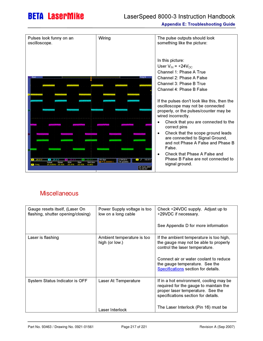
The pulse outputs should look something like the picture:
In this picture:
User VIN = +24VDC
Channel 1: Phase A True
Channel 2: Phase A False
Channel 3: Phase B True
Channel 4: Phase B False
If the pulses don't look like this, then the oscilloscope may not be connected properly, or the pulses/counter may be wired incorrectly.
•Check that you are connected to the correct pins
•Check that the scope ground leads are connected to Signal Ground, and not Phase A False and Phase B False.
•Check that Phase A False and Phase B False are not connected to signal ground.
Miscellaneous
Gauge resets itself, (Laser On | Power Supply voltage is too |
flashing, shutter opening/closing) | low on a long cable |
Laser is flashing | Ambient temperature is too |
| high (or low.) |
System Status Indicator is OFF | Laser At Temperature |
Laser Interlock
Check +24VDC supply. Adjust up to +29VDC if necessary.
See Appendix D for more information
If the ambient temperature is too high, the gauge may not be able to properly control the laser temperature.
Connect air or water coolant to reduce the gauge temperature. See the Specifications section for details.
If in a hot environment, cooling may be required for the gauge to maintain the proper laser temperature. See the specifications section for details.
The Laser Interlock (Pin 16) must be
Part No. 93463 / Drawing No. | Page 217 of 221 | Revision A (Sep 2007) |