LaserSpeed
Interfacing with the
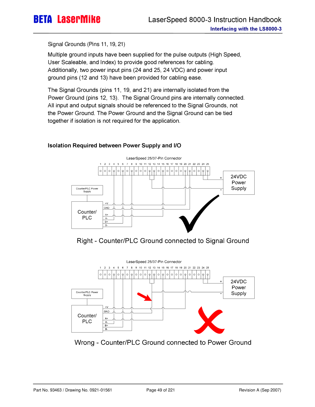
Signal Grounds (Pins 11, 19, 21)
Multiple ground inputs have been supplied for the pulse outputs (High Speed, User Scaleable, and Index) to provide good references for cabling. Additionally, two power input pins (24 and 25, 24 VDC) and power input ground pins (12 and 13) have been provided for cabling ease.
The Signal Grounds (pins 11, 19, and 21) are internally isolated from the Power Ground (pins 12, 13). The Signal Ground pins are internally connected. All input and output signals should be referenced to the Signal Grounds, not the Power Ground. The Power Ground and the Signal Ground can be tied together if isolation is not required for the application.
Isolation Required between Power Supply and I/O
Part No. 93463 / Drawing No. | Page 49 of 221 | Revision A (Sep 2007) |