LaserSpeed
Interfacing with the
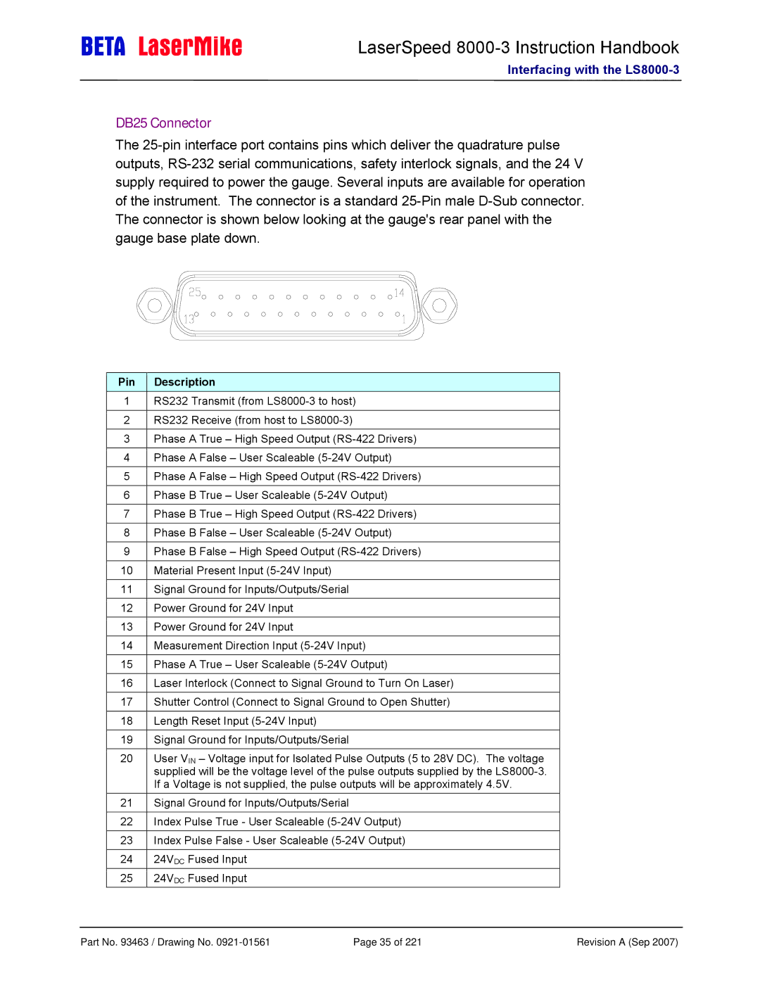
DB25 Connector
The
Pin | Description |
|
|
1RS232 Transmit (from
2RS232 Receive (from host to
3Phase A True – High Speed Output
4Phase A False – User Scaleable
5Phase A False – High Speed Output
6Phase B True – User Scaleable
7Phase B True – High Speed Output
8Phase B False – User Scaleable
9Phase B False – High Speed Output
10 Material Present Input
11 Signal Ground for Inputs/Outputs/Serial
12 Power Ground for 24V Input
13 Power Ground for 24V Input
14 Measurement Direction Input
15 Phase A True – User Scaleable
16 Laser Interlock (Connect to Signal Ground to Turn On Laser) 17 Shutter Control (Connect to Signal Ground to Open Shutter) 18 Length Reset Input
19 Signal Ground for Inputs/Outputs/Serial
20User VIN – Voltage input for Isolated Pulse Outputs (5 to 28V DC). The voltage supplied will be the voltage level of the pulse outputs supplied by the
21Signal Ground for Inputs/Outputs/Serial
22Index Pulse True - User Scaleable
23Index Pulse False - User Scaleable
2424VDC Fused Input
2524VDC Fused Input
Part No. 93463 / Drawing No. | Page 35 of 221 | Revision A (Sep 2007) |