VENT/FLUE PIPE & COMBUSTION AIR PIPE

NON-DIRECTVENT(SINGLEPIPE)PIPING

Non-direct vent installations require only a vent/flue pipe. The vent pipe can be run horizontally with an exit through the side of the building or run vertically with an exit through the roof of the building. The vent can also be run through an existing unused chimney; however, it must extend a minimum of 12 inches above the top of the chimney. The space between the vent pipe and the chimney must be closed with a weather-tight, corrosion-resistant flashing. For details concerning connection of the vent/flue pipe to the fur- nace, refer to Vent/Flue Pipe and Combustion Air - Standard Fur- nace Connections or Alternate Furnace Connections for specific details. Refer to the following Non-Direct Vent (Single Pipe) Piping

-Vent/Flue Pipe Terminations for specific details on termination construction.

Although non-direct vent installations do not require a combustion air intake pipe, a minimum of one 90° elbow should be attached to the furnace’s combustion air intake if: an upright installation uses the standard intake location, or a horizontal installation uses the alternate air intake location. This elbow will guard against inadvert- ent blockage of the air intake.

VENT/FLUE PIPE LENGTHS AND DIAMETERS

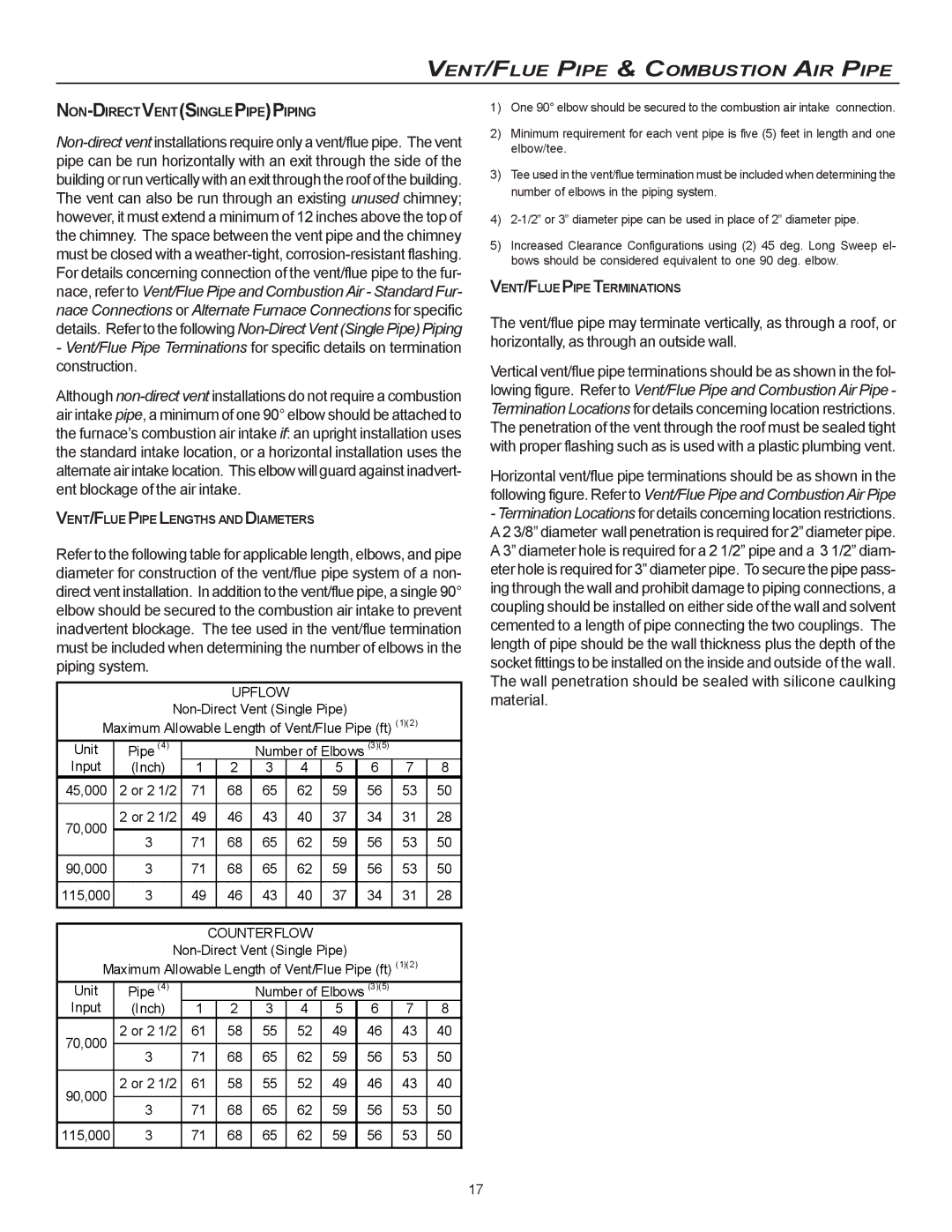
Refer to the following table for applicable length, elbows, and pipe diameter for construction of the vent/flue pipe system of a non- direct vent installation. In addition to the vent/flue pipe, a single 90° elbow should be secured to the combustion air intake to prevent inadvertent blockage. The tee used in the vent/flue termination must be included when determining the number of elbows in the piping system.

UPFLOW

Non-Direct Vent (Single Pipe)

Maximum Allowable Length of Vent/Flue Pipe (ft) (1)(2)

Unit

Pipe

(4)


Number of Elbows (3)(5)


Input

(Inch)

1


2

3

4

5

6

7

8

45,000

2 or 2

1/2

71


68

65

62

59

56

53

50


70,000

2 or 2

1/2

49


46

43

40

37

34

31

28

3


71


68

65

62

59

56

53

50


90,000

3


71


68

65

62

59

56

53

50


115,000

3


49


46

43

40

37

34

31

28


COUNTERFLOW


Non-Direct Vent (Single Pipe)


Maximum Allowable Length of Vent/Flue Pipe (ft) (1)(2)


Unit

Pipe

(4)


Number of Elbows (3)(5)


Input

(Inch)

1


2

3

4

5

6

7

8

70,000

2 or 2

1/2

61


58

55

52

49

46

43

40


3


71


68

65

62

59

56

53

50


90,000

2 or 2

1/2

61


58

55

52

49

46

43

40


3


71


68

65

62

59

56

53

50


115,000

3


71


68

65

62

59

56

53

50


1)One 90° elbow should be secured to the combustion air intake connection.

2)Minimum requirement for each vent pipe is five (5) feet in length and one elbow/tee.

3)Tee used in the vent/flue termination must be included when determining the number of elbows in the piping system.

4)2-1/2” or 3” diameter pipe can be used in place of 2” diameter pipe.

5)Increased Clearance Configurations using (2) 45 deg. Long Sweep el- bows should be considered equivalent to one 90 deg. elbow.

VENT/FLUE PIPE TERMINATIONS

The vent/flue pipe may terminate vertically, as through a roof, or horizontally, as through an outside wall.

Vertical vent/flue pipe terminations should be as shown in the fol- lowing figure. Refer to Vent/Flue Pipe and Combustion Air Pipe - Termination Locations for details concerning location restrictions. The penetration of the vent through the roof must be sealed tight with proper flashing such as is used with a plastic plumbing vent.

Horizontal vent/flue pipe terminations should be as shown in the following figure. Refer to Vent/Flue Pipe and Combustion Air Pipe

-Termination Locations for details concerning location restrictions. A 2 3/8” diameter wall penetration is required for 2” diameter pipe. A 3” diameter hole is required for a 2 1/2” pipe and a 3 1/2” diam- eter hole is required for 3” diameter pipe. To secure the pipe pass- ing through the wall and prohibit damage to piping connections, a coupling should be installed on either side of the wall and solvent cemented to a length of pipe connecting the two couplings. The length of pipe should be the wall thickness plus the depth of the socket fittings to be installed on the inside and outside of the wall. The wall penetration should be sealed with silicone caulking material.

17

Page 17
Image 17
Goodman Mfg CVC9/95, MVC95 installation instructions Upflow, Non-Directventsinglepipepiping

MVC95, CVC9/95 specifications

Goodman Manufacturing has established itself as a leader in the HVAC industry, and among its stellar lineup, the Goodman CVC9/95 and MVC95 stand out for their remarkable features, technologies, and efficiency.

The Goodman CVC9/95 is a high-performance gas furnace, designed for homeowners seeking reliability and cost-effective heating solutions. It operates with an impressive 95% Annual Fuel Utilization Efficiency (AFUE), which means that a significant portion of the fuel it consumes is converted into heat. This level of efficiency not only contributes to lower energy bills but also reduces greenhouse gas emissions, making it an environmentally friendly choice.

One of the standout features of the CVC9/95 is its multi-speed ECM blower motor. This technology adjusts the airflow according to the heating demands of the home, ensuring consistent and comfortable temperatures. The ECM motor also operates quietly, enhancing the comfort of your living space without the disruptive noise often associated with traditional furnaces.

The MVC95, on the other hand, offers similar efficiency with its also 95% AFUE rating. This model is equipped with a patented ignition system that enhances reliability with minimal maintenance needs. Its durable construction includes a heavy-gauge steel cabinet and an insulated blower compartment that minimizes heat loss. This design not only supports optimal performance but also contributes to its longevity.

Both models come with a self-diagnostic control board that provides straightforward troubleshooting capabilities, making it easier for technicians to ensure that your system is operating at peak performance. This feature aids in timely maintenance, which is crucial for extending the lifespan of the unit.

Additionally, Goodman backs their products with a strong warranty, offering a lifetime limited warranty on the heat exchanger and a 10-year limited parts warranty. This assurance provides homeowners peace of mind regarding their investment.

In the landscape of HVAC solutions, the Goodman CVC9/95 and MVC95 models exemplify a commitment to quality, efficiency, and advanced technology. Whether for new constructions or replacements, these furnaces offer superior heating performance coupled with modern conveniences, making them an invaluable choice for homeowners seeking effective climate control solutions. With their low emissions and high efficiency, choosing Goodman means investing in both comfort and sustainability.