SERVICING

S-1 CHECKING VOLTAGE

1.Remove doors, control panel cover, etc. from unit being tested.

With power ON:

LINE VOLTAGE NOW PRESENT.

2.Using a voltmeter, measure the voltage across terminals L1 and L2 of the contactor for single phase units, and L3, for 3 phase units.

3.No reading - indicates open wiring, open fuse(s) no power or etc. from unit to fused disconnect service. Repair as needed.

4.With ample voltage at line voltage connectors, energize the unit.

5.Measure the voltage with the unit starting and operating, and determine the unit Locked Rotor Voltage.

Locked Rotor Voltage is the actual voltage available at the compressor during starting, locked rotor, or a stalled condition. Measured voltage should be above minimum listed in chart below.

To measure Locked Rotor Voltage attach a voltmeter to the run "R" and common "C" terminals of the compres- sor, or to the T1 and T2 terminals of the contactor. Start the unit and allow the compressor to run for several sec- onds, then shut down the unit. Immediately attempt to restart the unit while measuring the Locked Rotor Volt- age.

6.Should read within the voltage tabulation as shown. If the voltage falls below the minimum voltage, check the line wire size. Long runs of undersized wire can cause low voltage. If wire size is adequate, notify the local power company in regards to either low or high voltage.

Unit Supply Voltage

Voltage Min. Max.

460 437 506

208/230 198 253

Three phase units require a balanced 3 phase power supply to operate. If the percentage of voltage imbalance exceeds 3% the unit must not be operated until the voltage condition is corrected.

% Voltage =

Max. Voltage Deviation

From Average Voltage X 100

Imbalance

Average Voltage

To find the percentage of imbalance, measure the incoming

power supply.


L1 - L2 = 240V


L1 - L3 = 232V

Avg. V = 710 = 236.7

L2 - L3 = 238V

3

Total

710V


To find Max. deviation:

240 - 236.7 = +3.3


232 - 236.7 = -4.7


238 - 236.7 = +1.3

Max deviation was 4.7V

% Voltage Imbalance = 4.7 = 1.99% 236.7

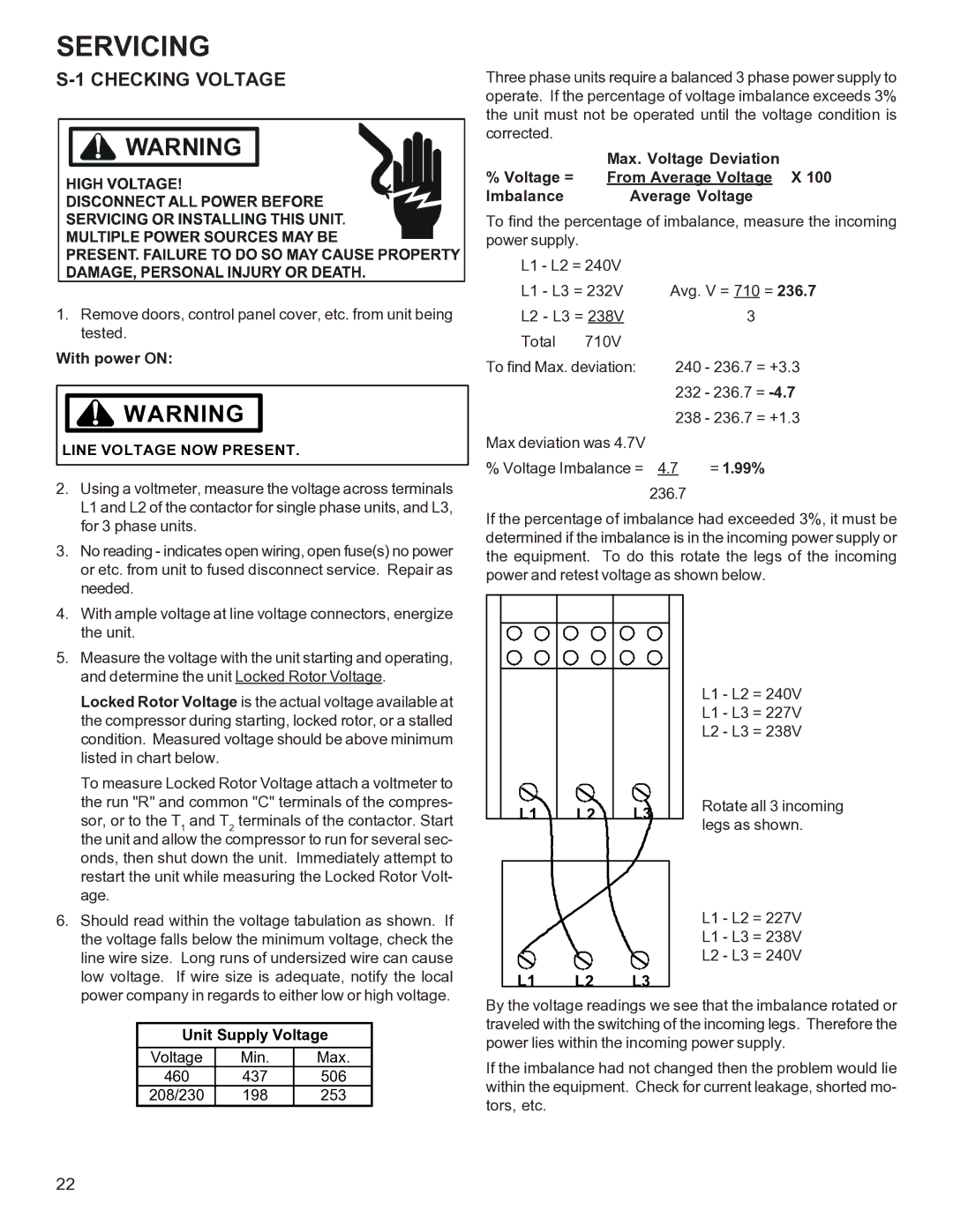
If the percentage of imbalance had exceeded 3%, it must be determined if the imbalance is in the incoming power supply or the equipment. To do this rotate the legs of the incoming power and retest voltage as shown below.

L1 - L2 = 240V

L1 - L3 = 227V

L2 - L3 = 238V

L1

L2

L3

Rotate all 3 incoming

legs as shown.


L1 - L2 = 227V

L1 - L3 = 238V

L2 - L3 = 240V

L1 L2 L3

By the voltage readings we see that the imbalance rotated or traveled with the switching of the incoming legs. Therefore the power lies within the incoming power supply.

If the imbalance had not changed then the problem would lie within the equipment. Check for current leakage, shorted mo- tors, etc.

22

Page 22
Image 22
Goodman Mfg R-410A manual Checking Voltage, Line Voltage NOW Present

R-410A specifications

Goodman Manufacturing, a well-respected name in the HVAC industry, has made significant advancements with their R-410A refrigerant technology. R-410A, a hydrofluorocarbon (HFC), has positioned itself as a superior alternative to the older R-22 refrigerant, which has been phased out due to its ozone-depleting properties. Goodman’s commitment to energy efficiency and environmental sustainability is well reflected in their use of R-410A in their air conditioning and heat pump systems.

One of the main features of Goodman’s R-410A systems is their exceptional energy efficiency. The R-410A refrigerant operates at a higher pressure than R-22, which allows for better heat transfer and improved cooling capacity. This results in reduced energy consumption and lower utility bills for consumers. Goodman’s air conditioning units designed for use with R-410A are often rated with high Seasonal Energy Efficiency Ratio (SEER) ratings, making them an eco-friendly choice for residential and commercial applications.

Another notable technology employed by Goodman is their commitment to reliable performance through advanced compressor designs. Goodman's scroll compressors are optimized for R-410A, ensuring quieter operation and reducing vibration levels. These compressors are known for their efficiency and longevity, making them a favorite among homeowners seeking dependable and durable climate control solutions.

Goodman's multi-stage cooling systems that utilize R-410A offer precise temperature control and enhanced comfort. By controlling the speed of the compressor, Goodman’s units can adjust output according to the heating or cooling demand, maximizing comfort while minimizing energy waste. This adaptability not only enhances indoor air quality but also contributes to a greener environment by using less energy.

Furthermore, Goodman incorporates high-tech diagnostic controls into their systems. These controls provide real-time performance data, allowing homeowners and technicians to monitor system status and troubleshoot issues more easily. By using R-410A combined with these innovative technologies, Goodman emphasizes reliability and user-friendly operation.

In conclusion, Goodman Manufacturing’s use of R-410A refrigerant reflects their dedication to efficiency, reliability, and environmental stewardship in HVAC solutions. The combination of advanced compressor technologies, high energy efficiency, and innovative controls solidifies Goodman’s reputation as a leader in the industry, offering homeowners and businesses the comfort and peace of mind they deserve.