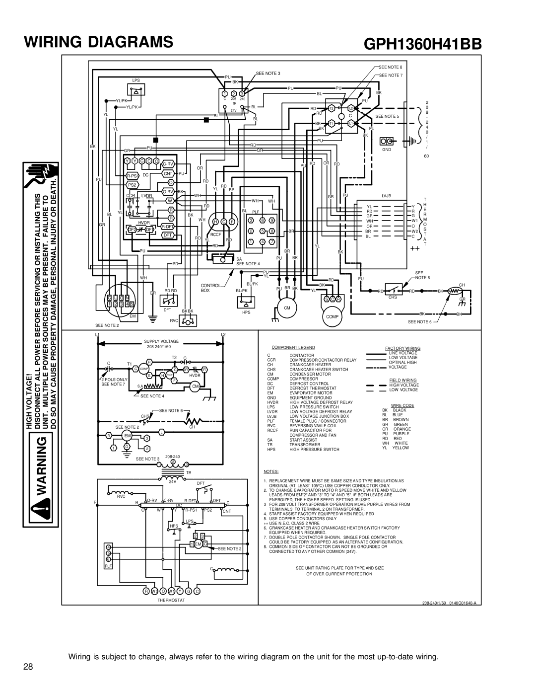
WIRING DIAGRAMS

GPH1360H41BB

OR INSTALLING THIS PRESENT. FAILURE TO PERSONAL INJURY OR DEATH.


SEE NOTE 8


PU


SEE NOTE 3


SEE NOTE 7


LPS


BK


1


PU

BL


PU

BK


2

3


YL/PK


C

208

240


PU


2


YL/PK


BL


24V


RD

T2

L2


0

YL


RD


8


BL


C

SEE NOTE 5


BL


BL


-


BK

T1

L1


2


4


YL


BK

PU


BK


0


BL


/


PU


BK


RD


1

GR

PU


GND

/


GR


Y Y

C C

C


60


C-RV


PU

RD

OR

RD


OR


PU

R-PS1

DC


CNT

PU

RD


O


PS2


YL RD


BR


O-RV

BK


PU


CCR

LVDR


WH


GR

LVJB

T


W


WH

WH


RD


H


YL


R


BL


R

E

BL

YL


BK


PLF


RD


R


GR

G

R


HVDR


WH

H

C

F

3

6

9


WH

W1

M

GR


O


R-DFT


OR

O


DF2

DF1


2

5

8

BR


S


BR

W2


DFT


RCCF


T


RD


BL

C


YL


RD

1

4

7


A


RD


YL


++

T


PU


BR


BK


SA


PU

BK


RD


SEE NOTE 4


BEFORE SERVICING SOURCES MAY BE PROPERTY DAMAGE,


WH


CONTROL


GR

RD RD

BOX

C

L

G N


1

2

3

4

5


EM

DFT

BK BK


RVC


SEE NOTE 2


L1


L2


SUPPLY VOLTAGE


BL/PK BL/PK

HPS

PU


SEE


YL


RD

PU

NOTE 6


BK


CH

PU

BR

BK


YL


RD

RD

BK


S C R


CHS

GR


CM


COMP


BK

BK


SEE NOTE 6


VOLTAGE! ALL POWER MULTIPLE POWER MAY CAUSE


208-240/1/60


C


R

T2

C

T1


C COMP


C


2 POLE ONLY

S

H RCCF

HVDR


F


SEE NOTE 7


S.A.


CM


SEE NOTE 4

COMPONENT LEGEND

C

CONTACTOR

CCR

COMPRESSOR CONTACTOR RELAY

CH

CRANKCASE HEATER

CHS

CRANKCASE HEATER SWITCH

CM

CONDENSER MOTOR

COMP

COMPRESSOR

DC

DEFROST CONTROL

DFT

DEFROST THERMOSTAT

EM

EVAPORATOR MOTOR

GND

EQUIPMENT GROUND

HVDR

HIGH VOLTAGE DEFROST RELAY

FACTORY WIRING

LINE VOLTAGE

LOW VOLTAGE

OPTINAL HIGH VOLTAGE

FIELD WIRING

HIGH VOLTAGE

LOW VOLTAGE

HIGH DISCONNECT WARNING UNIT. DO SO


SEE NOTE 6


CHS


SEE NOTE 2

L

CH

N

EM


3


1

G

2


SEE NOTE 3

208-240


2


1

3


TR

LPS

LOW PRESSURE SWITCH

LVDR

LOW VOLTAGE DEFROST RELAY

LVJB

LOW VOLTAGE JUNCTION BOX

PLF

FEMALE PLUG / CONNECTOR

RVC

REVERSING VAVLE COIL

RCCF

RUN CAPACITOR FOR

SA

COMPRESSOR AND FAN

START ASSIST

TR

TRANSFORMER

HPS

HIGH PRESSURE SWITCH

NOTES:


WIRE CODE

BK

BLACK

BL

BLUE

BR

BROWN

GR

GREEN

OR

ORANGE

PU

PURPLE

RD

RED

WH

WHITE

YL

YELLOW


24V

DFT


RVC

O-RV

C-RV

R-DFT


DFT


R

R


C


DC


R-PS1


O

W

Y

PS2


CNT


HPS

LPS


2

3


4


1 EM C

SEE NOTE 2


5


6


PLF


C


1.REPLACEMENT WIRE MUST BE SAME SIZE AND TYPE INSULATION AS ORIGINAL (AT LEAST 105°C) USE COPPER CONDUCTOR ONLY.

2.TO CHANGE EVAPORATOR MOTO R SPEED MOVE WHITE AND YELLOW LEADS FROM EM"2" AND "3" TO "4" AND "5". IF BOTH LEADS ARE

ENERGIZED, THE HIGHER SPEED SETTING IS USED.

3 FOR 208 VOLT TRANSFORMER O PERATION MOVE PURPLE WIRES FROM TERMINAL 3 TO TERMINAL 2 ON TRANSFORMER.

4.START ASSIST FACTORY EQUIPPED WHEN REQUIRED

5.USE COPPER CONDUCTORS ONLY

++ USE N.E.C. CLASS 2 WIRE

6.CRANKCASE HEATER AND CRANKCASE HEATER SWITCH FACTORY EQUIPPED WHEN REQUIRED.

7.DOUBLE POLE CONTACTOR SHOWN. SINGLE POLE CONTACTOR COULD BE FACTORY EQUIPPED AS AN ALTERNATE CONFIGURATION.

8.COMMON SIDE OF CONTACTOR CAN NOT BE GROUNDED OR CONNECTED TO ANY OTHER COMMON (24V).

SEE UNIT RATING PLATE FOR TYPE AND SIZE

OF OVER CURRENT PROTECTION

R

W 2 O W 1 Y

G

C


THERMOSTAT


208-240/1/60 0140G01640-A


Wiring is subject to change, always refer to the wiring diagram on the unit for the most up-to-date wiring.

28

Page 28
Image 28
Goodmans Package Heat Pump Units, GPH 13 H service manual GPH1360H41BB, Before Servicing Sources MAY be Property Damage

GPH 13 H, Package Heat Pump Units specifications

Goodmans Package Heat Pump Units, specifically the GPH 13 H model, represent an advanced solution in residential and commercial climate control. Known for their efficiency and reliability, these heat pumps offer a combination of heating and cooling capabilities, making them ideal for year-round comfort.

One of the standout features of the GPH 13 H is its energy efficiency rating. With a SEER (Seasonal Energy Efficiency Ratio) of 13, it efficiently converts energy into heating and cooling, which can lead to significant savings on utility bills. This efficiency is not only beneficial for homeowners looking to reduce their energy footprint, but it also qualifies for many energy rebate programs.

Durability is another hallmark of the GPH 13 H. Built with robust materials, the unit is designed to withstand various weather conditions, ensuring longevity and reliable performance. Components are treated to resist corrosion, which extends the lifespan of the heat pump and enhances its efficiency.

The GPH 13 H utilizes innovative inverter technology, allowing it to adjust its cooling and heating output according to the space's specific needs. This results in more consistent temperatures and improved indoor comfort. Additionally, the variable-speed compressor operates at different levels, reducing energy consumption while providing effective heating and cooling.

In terms of installation, the GPH 13 H offers versatility. Its compact design facilitates easy placement in various locations, making it suitable for both new construction and retrofitting existing spaces. The unit's all-in-one design simplifies installation by minimizing the need for external ductwork.

Quiet operation is a critical consideration for many homeowners, and Goodmans excels in this area. The GPH 13 H is engineered to minimize noise levels, ensuring a peaceful indoor environment. This feature makes it an excellent choice for residential areas where noise may be a concern.

The unit also features advanced control systems, including programmable thermostats that allow users to set specific temperature schedules. This feature not only enhances user comfort but also contributes to energy savings by preventing unnecessary heating or cooling when spaces are unoccupied.

Overall, Goodmans Package Heat Pump Units, GPH 13 H, combine efficiency, durability, and advanced technology to deliver a reliable climate control solution. With its focus on energy savings, quiet operation, and flexibility in installation, this model stands out as a leading choice for those seeking optimal home comfort. Its thoughtful design and engineering make it a worthwhile investment in both residential and commercial settings.