Manuals
/
Graco
/
Household Appliance
/
Thermostat
Graco
308791E Table of Contents, Setup, Install the Elbow Fitting and Tubing, Parts
Models:
308791E
1
2
12
12
Download
12 pages
39.71 Kb
1
2
3
4
5
6
7
8
Parts list
Warranty
Maintenance
Accessories
Remote Air Regulator Assembly
Pressure Relief Procedure
Weight
Page 2
Image 2
Page 1
Page 3
Page 2
Image 2
Page 1
Page 3
Contents
Single Air Regulator
Instructions - Parts List
Important Safety Instructions
Double Air Regulator
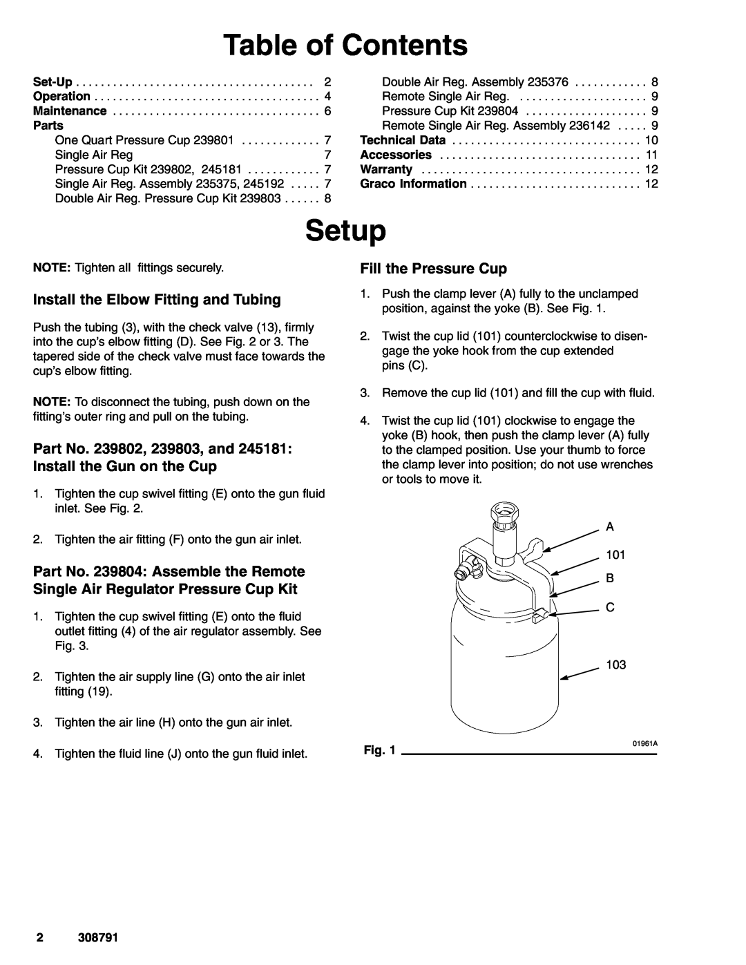
Install the Elbow Fitting and Tubing
Table of Contents
Setup
Part No. 239802, 239803, and 245181 Install the Gun on the Cup
7612A
308791
7611A
7623A
Pressure Relief Procedure
Setting the Cup Air Pressure
Setting the Gun Air Pressure
Operation
Optional Gun Air Regulator
Disconnect the Gun and Air Regulator from the Cup
Maintenance
1. Follow the Pressure Relief Procedure Warning on page
Remove the Cup Lid
See parts list at right
Use Only Genuine Graco Parts and Accessories
Single Air Regulator Assembly Part No. 235375, Series B
See parts list above
See parts list, page
Double Air Regulator Assembly Part No. 235376, Series B
See parts list below
Double Air Regulator Pressure Cup Kit
Pressure Cup Kit
Remote Air Regulator Assembly
Remote Single Air Regulator
Part No. 236142, Series B
Weight without gun
Technical Data
Weight
Single Air Regulator Pressure Cup Kit, Part No. 239802 and
100 psi 7 bar Maximum Outlet Pressure
Accessories
Spray Gun Air Regulator Assembly
150 psi 10 bar Maximum Inlet Pressure
FOR GRACO CANADA CUSTOMERS
Graco Standard Warranty
Graco Information
Graco reserves the right to make changes at any time without notice
Top
Page
Image
Contents