Pressure Relief Procedure
Pump to Fluid Manifold
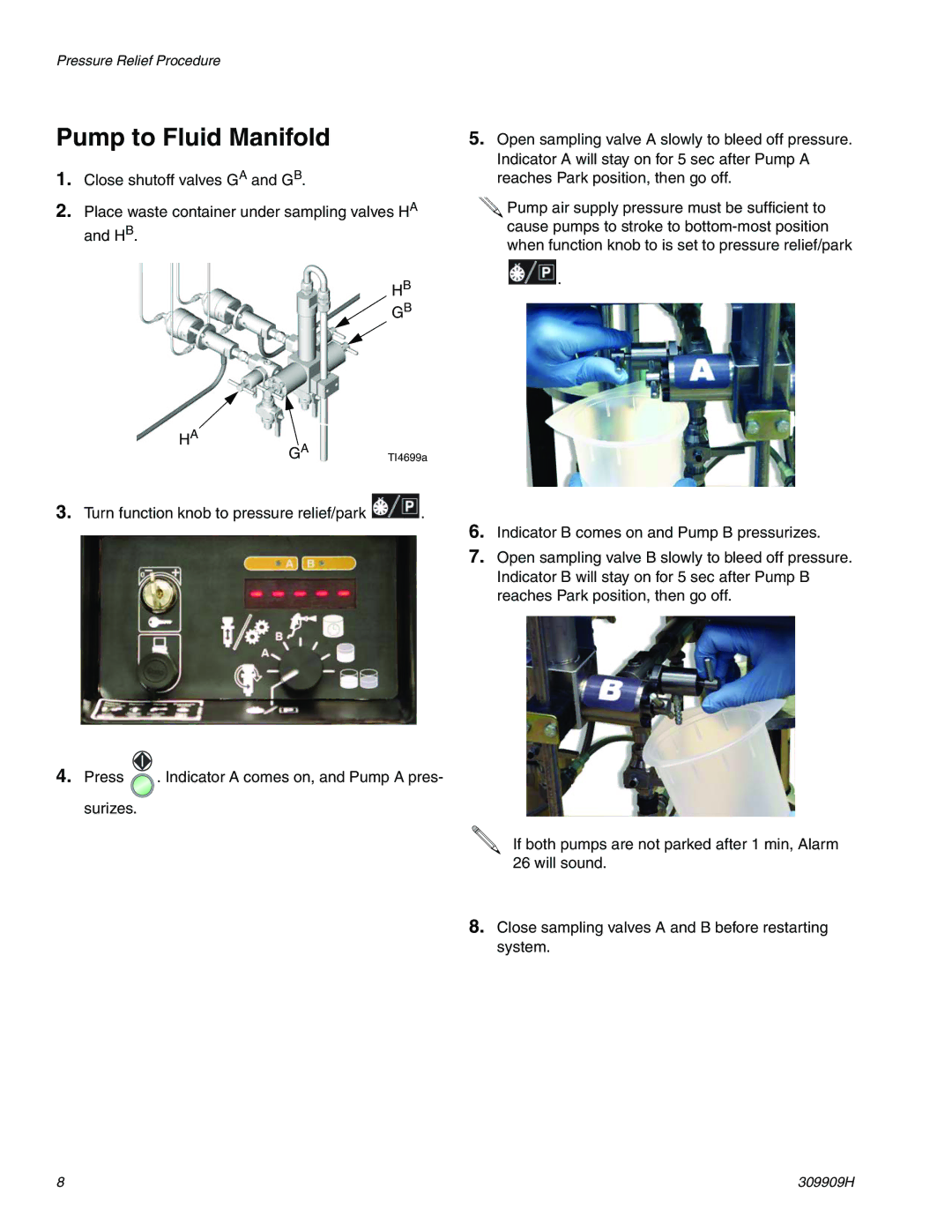
1.Close shutoff valves GA and GB.
2.Place waste container under sampling valves HA and HB.
5.Open sampling valve A slowly to bleed off pressure. Indicator A will stay on for 5 sec after Pump A reaches Park position, then go off.
![]() Pump air supply pressure must be sufficient to cause pumps to stroke to
Pump air supply pressure must be sufficient to cause pumps to stroke to
HA
HB
![]() GB
GB
GATI4699a
![]() .
.
3.Turn function knob to pressure relief/park ![]() .
.
4.Press ![]() . Indicator A comes on, and Pump A pres- surizes.
. Indicator A comes on, and Pump A pres- surizes.
6.Indicator B comes on and Pump B pressurizes.
7.Open sampling valve B slowly to bleed off pressure. Indicator B will stay on for 5 sec after Pump B reaches Park position, then go off.
If both pumps are not parked after 1 min, Alarm 26 will sound.
8.Close sampling valves A and B before restarting system.
8 | 309909H |
