Parts
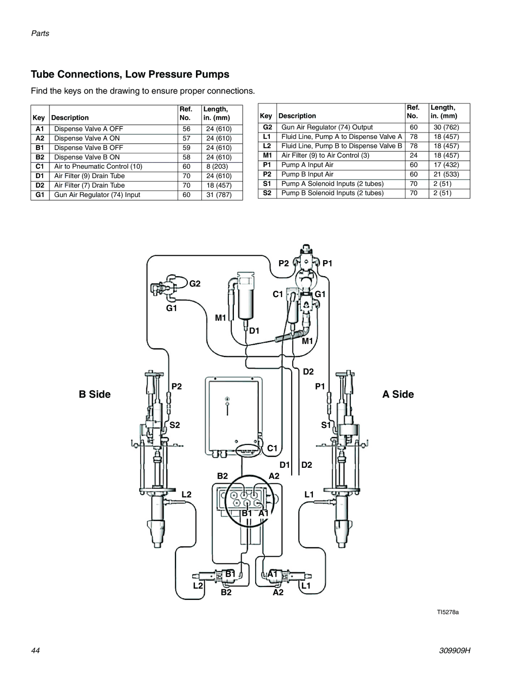
Tube Connections, Low Pressure Pumps
Find the keys on the drawing to ensure proper connections.
|
| Ref. | Length, |
Key | Description | No. | in. (mm) |
|
|
|
|
A1 | Dispense Valve A OFF | 56 | 24 (610) |
|
|
|
|
A2 | Dispense Valve A ON | 57 | 24 (610) |
B1 | Dispense Valve B OFF | 59 | 24 (610) |
B2 | Dispense Valve B ON | 58 | 24 (610) |
|
|
|
|
C1 | Air to Pneumatic Control (10) | 60 | 8 (203) |
D1 | Air Filter (9) Drain Tube | 70 | 24 (610) |
D2 | Air Filter (7) Drain Tube | 70 | 18 (457) |
|
|
|
|
G1 | Gun Air Regulator (74) Input | 60 | 31 (787) |
|
| Ref. | Length, |
Key | Description | No. | in. (mm) |
|
|
|
|
G2 | Gun Air Regulator (74) Output | 60 | 30 (762) |
L1 | Fluid Line, Pump A to Dispense Valve A | 78 | 18 (457) |
|
|
|
|
L2 | Fluid Line, Pump B to Dispense Valve B | 78 | 18 (457) |
M1 | Air Filter (9) to Air Control (3) | 24 | 18 (457) |
P1 | Pump A Input Air | 60 | 17 (432) |
|
|
|
|
P2 | Pump B Input Air | 60 | 21 (533) |
S1 | Pump A Solenoid Inputs (2 tubes) | 70 | 2 (51) |
S2 | Pump B Solenoid Inputs (2 tubes) | 70 | 2 (51) |
|
|
|
|
|
|
|
|
|
|
| P2 | P1 | |
G2 |
|
|
|
|
| ||||
|
|
|
|
|
|
| C1 | G1 | |
G1 |
|
|
|
|
| ||||
M1 |
|
|
|
|
| ||||
|
|
| D1 |
| |||||
|
|
|
|
|
|
|
|
| M1 |
|
|
|
|
|
|
|
|
| D2 |
P2 |
|
|
|
| P1 | ||||
B Side |
|
|
|
| A Side | ||||
S2 |
|
|
|
| S1 | ||||
|
|
|
|
| C1 |
| |||
|
|
|
|
|
|
| D1 | D2 | |
|
|
|
|
|
|
|
|
| |
B2 |
| A2 |
| ||||||
L2 |
|
|
|
| L1 | ||||
|
|
|
|
|
|
|
|
|
|
B1 | A1 |
| |||||||
| B1 |
| A1 |
|
L2 |
|
| L1 | |
B2 |
| A2 | ||
TI5278a
44 | 309909H |
