Replace a Solenoid
1.Remove air supply pressure from the system. Remove the color change module cover (30).
2.Disconnect the 2 solenoid wires from the color change board (15). See FIG. 7, the Color Change Module Electrical Schematic on page 15, and the System Electrical Schematic on page 17.
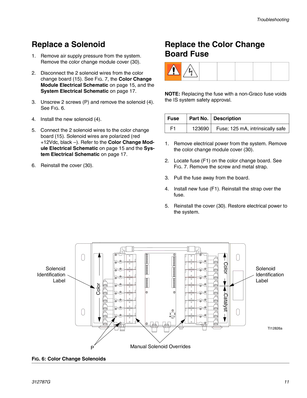
3.Unscrew 2 screws (P) and remove the solenoid (4). See FIG. 6.
4.Install the new solenoid (4).
5.Connect the 2 solenoid wires to the color change board (15). Solenoid wires are polarized (red +12Vdc, black
6.Reinstall the cover (30).
Troubleshooting
Replace the Color Change Board Fuse
NOTE: Replacing the fuse with a
Fuse | Part No. | Description |
|
|
|
F1 | 123690 | Fuse; 125 mA, intrinsically safe |
|
|
|
1.Remove electrical power from the system. Remove the color change module cover (30).
2.Locate fuse (F1) on the color change board. See FIG. 7. Remove the screw and metal strap.
3.Pull the fuse away from the board.
4.Install new fuse (F1). Reinstall the strap over the fuse.
5.Reinstall the cover (30). Restore electrical power to the system.
Solenoid | Color | Solenoid |
| ||
Identification |
| Identification |
Label |
| Label |
Color | Catalyst |
|
|
| TI12826a |
P | Manual Solenoid Overrides |
FIG. 6: Color Change Solenoids
312787G | 11 |