Troubleshooting
Table 4: Color Change Board Diagnostics
| Connector | Board 1 Signal | Board 2 Signal |
| |
LED | and Pin Nos. | Description | Description | Diagnosis | |
|
|
|
|
| |
D8 | n/a | Board OK | Board OK | Blinks (heartbeat) during nor- | |
|
|
|
| mal operation. | |
|
|
|
|
| |
D9 | n/a | Communication (yellow) | Communication (yellow) | Turns on when board is com- | |
|
|
|
| municating with ProMix 2KS. | |
|
|
|
|
| |
D10 | J7 | Power | Power | Turns on when power is sup- | |
|
|
|
| plied to the board. | |
|
|
|
|
| |
D27 | J15, 5 & 6 | Color 3 | Color 16 |
| |
|
|
|
|
| |
D28 | J14, 3 & 4 | Color 1 | Color 14 |
| |
|
|
|
|
| |
D29 | J8, 5 & 6 | Color 6 | Color 19 |
| |
|
|
|
|
| |
D30 | J14, 1 & 2 | Color 2 | Color 15 |
| |
|
|
|
|
| |
D31 | J8, 3 & 4 | Color 7 | Color 20 |
| |
|
|
|
|
| |
D32 | J16, 3 & 4 | Catalyst 4 | Color 26 |
| |
|
|
|
|
| |
D33 | J8, 1 & 2 | Color 8 | Color 21 |
| |
|
|
|
|
| |
D34 | J9, 5 & 6 | Color 9 | Color 22 | D27 through D46 turn on when | |
|
|
|
| ||
D35 | J15, 3 & 4 | Color 4 | Color 17 | ||
ProMix 2KS sends a signal to | |||||
|
|
|
| ||
D36 | J14, 5 & 6 | Solvent (Color) | Color 13 | actuate the related solenoid | |
valve. | |||||
|
|
|
| ||
D37 | J10, 5 & 6 | Catalyst 2 | Color 28 | ||
| |||||
|
|
|
|
| |
D38 | J16, 1 & 2 | Catalyst 3 | Color 27 |
| |
|
|
|
|
| |
D39 | J16, 5 & 6 | Color 12 | Color 25 |
| |
|
|
|
|
| |
D41 | J15, 1 & 2 | Color 5 | Color 18 |
| |
|
|
|
|
| |
D43 | J9, 3 & 4 | Color 10 | Color 23 |
| |
|
|
|
|
| |
D44 | J9, 1 & 2 | Color 11 | Color 24 |
| |
|
|
|
|
| |
D45 | J10, 3 & 4 | Catalyst 1 | Color 29 |
| |
|
|
|
|
| |
D46 | J10, 1 & 2 | Solvent (Catalyst) | Color 30 |
| |
|
|
|
|
|
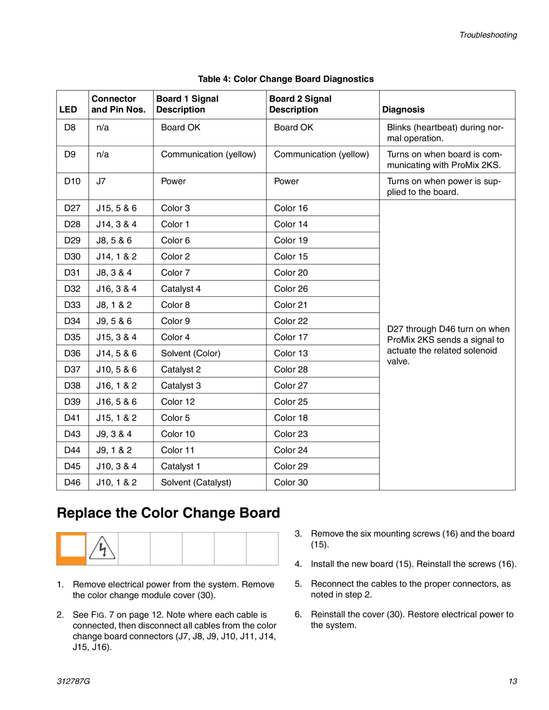
Replace the Color Change Board
1.Remove electrical power from the system. Remove the color change module cover (30).
2.See FIG. 7 on page 12. Note where each cable is connected, then disconnect all cables from the color change board connectors (J7, J8, J9, J10, J11, J14, J15, J16).
3.Remove the six mounting screws (16) and the board (15).
4.Install the new board (15). Reinstall the screws (16).
5.Reconnect the cables to the proper connectors, as noted in step 2.
6.Reinstall the cover (30). Restore electrical power to the system.
312787G | 13 |