Connect Module to Fluid Station Board
NOTICE
To avoid damaging circuit board when servicing, wear grounding strap on wrist and ground appropriately.
1.Remove the Fluid Station cover.
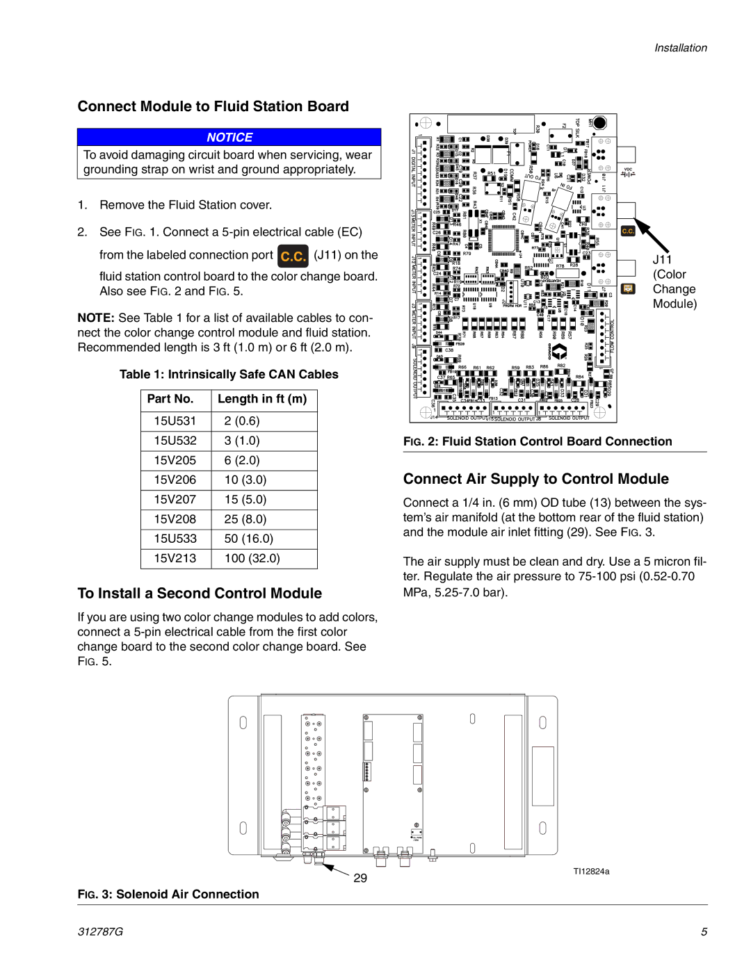
2.See FIG. 1. Connect a
from the labeled connection port ![]() (J11) on the fluid station control board to the color change board. Also see FIG. 2 and FIG. 5.
(J11) on the fluid station control board to the color change board. Also see FIG. 2 and FIG. 5.
NOTE: See Table 1 for a list of available cables to con- nect the color change control module and fluid station. Recommended length is 3 ft (1.0 m) or 6 ft (2.0 m).
Table 1: Intrinsically Safe CAN Cables
Part No. | Length in ft (m) | |
|
| |
15U531 | 2 (0.6) | |
|
| |
15U532 | 3 (1.0) | |
|
| |
15V205 | 6 (2.0) | |
|
|
|
15V206 | 10 | (3.0) |
|
|
|
15V207 | 15 | (5.0) |
|
|
|
15V208 | 25 | (8.0) |
|
|
|
15U533 | 50 | (16.0) |
|
| |
15V213 | 100 (32.0) | |
|
|
|
To Install a Second Control Module
If you are using two color change modules to add colors, connect a
Installation
J11
(Color Change Module)
FIG. 2: Fluid Station Control Board Connection
Connect Air Supply to Control Module
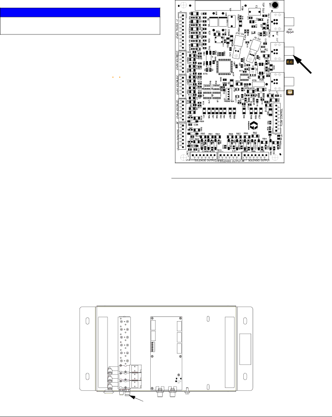
Connect a 1/4 in. (6 mm) OD tube (13) between the sys- tem’s air manifold (at the bottom rear of the fluid station) and the module air inlet fitting (29). See FIG. 3.
The air supply must be clean and dry. Use a 5 micron fil- ter. Regulate the air pressure to
29
FIG. 3: Solenoid Air Connection
TI12824a
312787G | 5 |