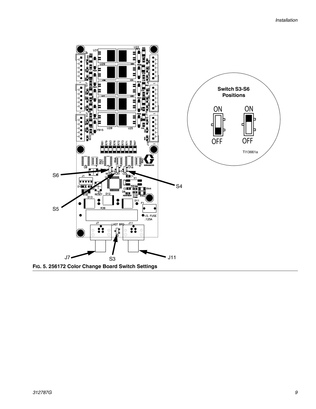
Manuals
/
Brands
/
TV and Video
/
CRT Television
/
Graco
/
TV and Video
/
CRT Television
Graco
312787G important safety instructions
- page 9
1
9
26
26
Download
26 pages, 1.7 Mb
Installation
312787G
9
F
IG
. 5. 256172 Color Change Board Switch Settings
OFF
ON
OFF
ON
S3
S4
S5
S6
J7 J11
Switch S3-S6
Positions
TI13661a
Contents
Main
312787G
Instructions-Parts
Color Change Module Kits
Contents
Related Manuals
Models
Low Pressure Kits
High Pressure Kits
Installation
Install Color Change Control Module
Location
Mounting
Connect Module to Fluid Station Board
To Install a Second Control Module
Connect Air Supply to Control Module
Page
Install Color Valve Stacks
Connect Valve Air Lines
Connect Valve Fluid Lines
Color Change Board Switch Settings
Accessory Dump Valve Kit
Table 2: Color Change Board Switch Settings for ProMix 2KS Systems Two Color Change Boards
Color Change Board 1 Color Change Board 2 Effect on System
S3 S6 S5 S4 S3 S6 S5 S4
One Color Change Board
Table 3: Color Change Board Switch Settings for ProMix 3KS Systems Two Color Change Boards
Page
Troubleshooting
Color Change Solenoid Valves
Color Change Board Fuse
Replace a Solenoid
Replace the Color Change Board Fuse
Color Change Board Diagnostics
Replace the Color Change Board
Schematic Diagrams
System Pneumatic Diagram
CONTROL AIR
PURGE AIR
TO MANIFOLD 1/4 TUBE
WIRING DIAGRAM
J8 J15 J14
J9 J16 J10
System Electrical Schematic
Non-Hazardous Area
I/O HARNESSES
CABLE
NON-HAZARDOUS AREA
System Electrical Schematic
Hazardous Area
J10
J1
HAZARDOUS AREA
Parts
Low Pressure Color Change Kits
High Pressure Color Change Kits
Color Change Kits Parts
Color Change Control Modules
(Ref. No. 101; see page 18)
Control Module Part Quantities
Page
277752 2-Color Control Module
278095 1 Catalyst/1 Flush Control Module (0 Color)
Dimensions
Technical Data
Graco Standard Warranty
Graco Information