Install Color Valve Stacks
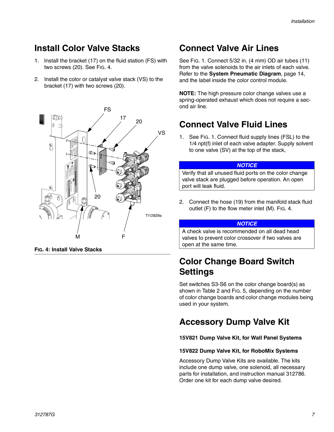
1.Install the bracket (17) on the fluid station (FS) with two screws (20). See FIG. 4.
2.Install the color or catalyst valve stack (VS) to the bracket (17) with two screws (20).
Installation
Connect Valve Air Lines
See FIG. 1. Connect 5/32 in. (4 mm) OD air tubes (11) from the valve solenoids to the air inlets of each valve. Refer to the System Pneumatic Diagram, page 14, and the label inside the color control module.
FS
17
20
MF
FIG. 4: Install Valve Stacks
20
VS
TI12829a
NOTE: The high pressure color change valves use a
Connect Valve Fluid Lines
1.See FIG. 1. Connect fluid supply lines (FSL) to the 1/4 npt(f) inlet of each valve adapter. Supply solvent to one valve (SV) at the top of the stack,
NOTICE
Verify that all unused fluid ports on the color change valve stack are plugged before operation. An open port will leak fluid.
2.Connect the hose (19) from the manifold stack fluid outlet (F) to the flow meter inlet (M). FIG. 4.
NOTICE
A check valve is recommended on all dead head valves to prevent color crossover if two valves are open at the same time.
Color Change Board Switch Settings
Set switches
Accessory Dump Valve Kit
15V821 Dump Valve Kit, for Wall Panel Systems
15V822 Dump Valve Kit, for RoboMix Systems
Accessory Dump Valve Kits are available. The kits include one dump valve, one solenoid, all necessary parts for installation, and instruction manual 312786. Order one kit for each dump valve desired.
312787G | 7 |