Install the Display Module
Install the Display Module
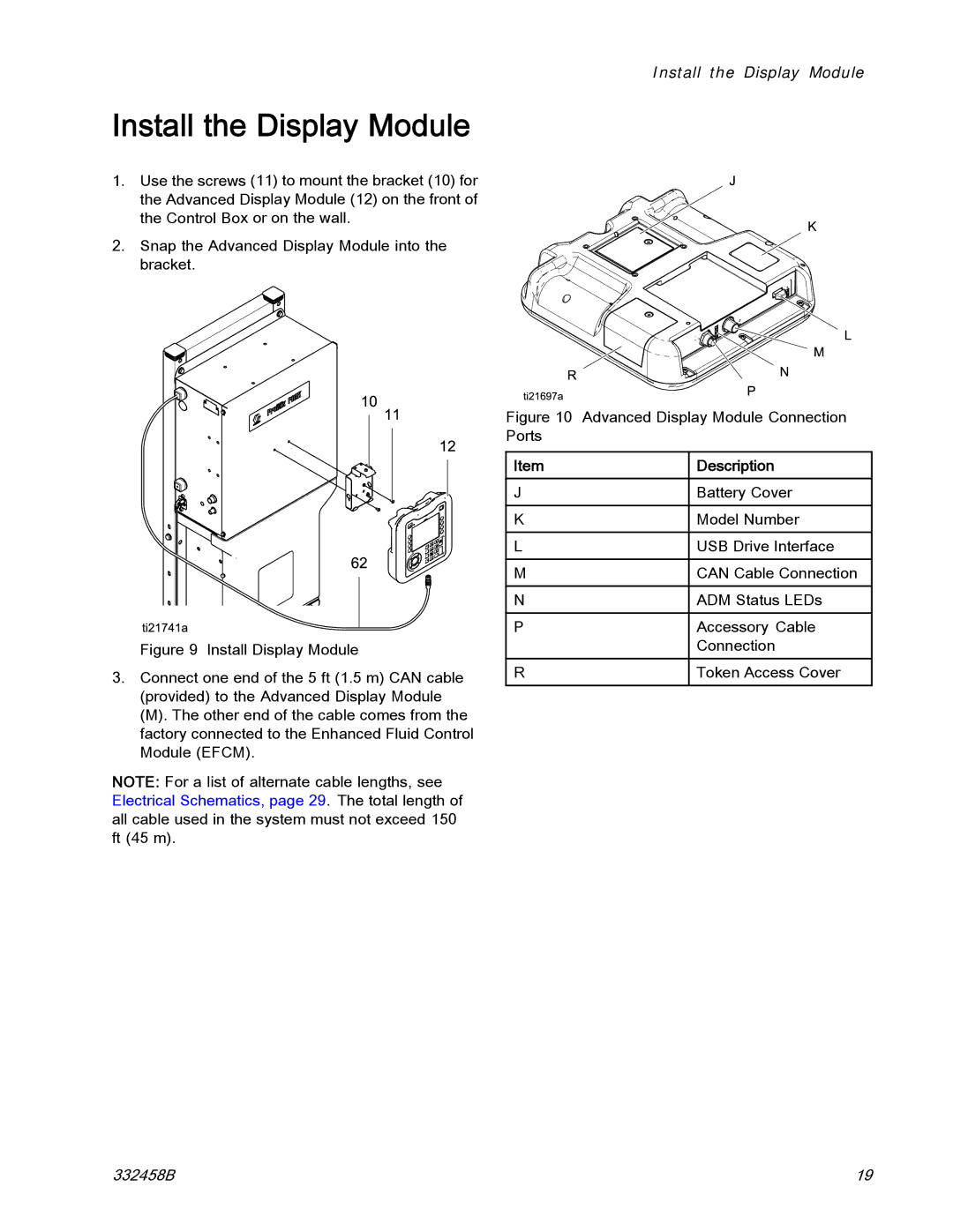
1. Use the screws (11) to mount the bracket (10) for the Advanced Display Module (12) on the front of the Control Box or on the wall.
2. Snap the Advanced Display Module into the bracket.
Figure 9 Install Display Module
3.Connect one end of the 5 ft (1.5 m) CAN cable (provided) to the Advanced Display Module
(M). The other end of the cable comes from the factory connected to the Enhanced Fluid Control Module (EFCM).
NOTE: For a list of alternate cable lengths, see Electrical Schematics, page 29. The total length of all cable used in the system must not exceed 150 ft (45 m).
Figure 10 Advanced Display Module Connection Ports
Item | Description |
J | Battery Cover |
K | Model Number |
L | USB Drive Interface |
M | CAN Cable Connection |
N | ADM Status LEDs |
P | Accessory Cable |
| Connection |
R | Token Access Cover |
|
|
332458B | 19 |
