Configure Your System
1. Select a Base Model
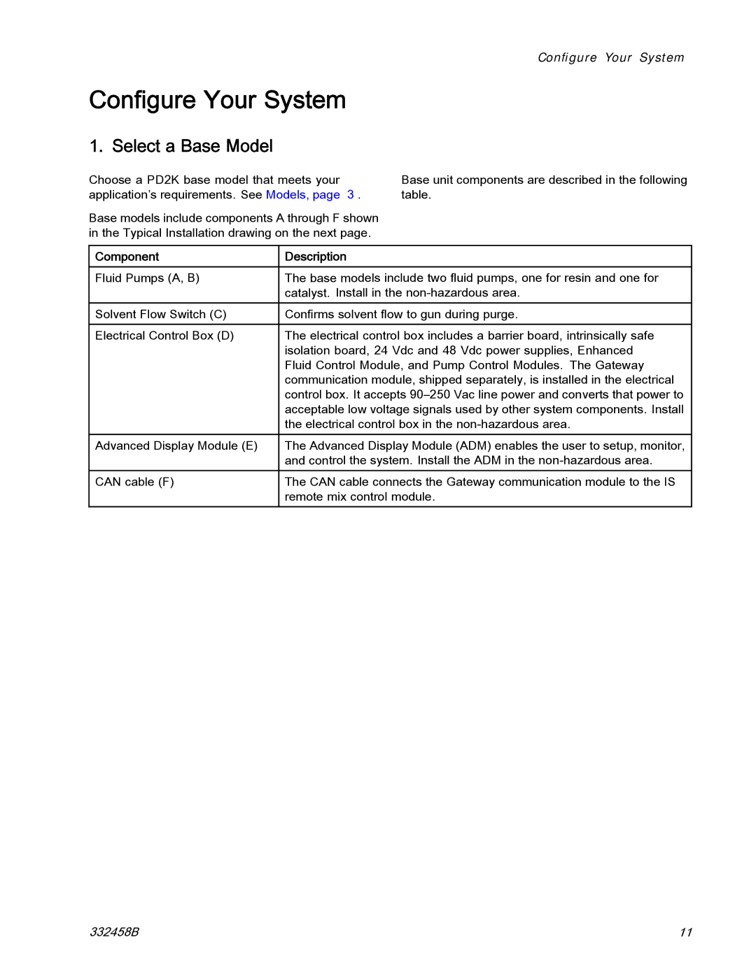
Choose a PD2K base model that meets your application’s requirements. See Models, page 3 .
Base models include components A through F shown in the Typical Installation drawing on the next page.
Configure Your System
Base unit components are described in the following table.
Component | Description |
|
|
Fluid Pumps (A, B) | The base models include two fluid pumps, one for resin and one for |
| catalyst. Install in the |
Solvent Flow Switch (C) | Confirms solvent flow to gun during purge. |
|
|
Electrical Control Box (D) | The electrical control box includes a barrier board, intrinsically safe |
| isolation board, 24 Vdc and 48 Vdc power supplies, Enhanced |
| Fluid Control Module, and Pump Control Modules. The Gateway |
| communication module, shipped separately, is installed in the electrical |
| control box. It accepts |
| acceptable low voltage signals used by other system components. Install |
| the electrical control box in the |
Advanced Display Module (E) | The Advanced Display Module (ADM) enables the user to setup, monitor, |
| and control the system. Install the ADM in the |
CAN cable (F) | The CAN cable connects the Gateway communication module to the IS |
| remote mix control module. |
332458B | 11 |
