Fluid Supply
Single Color Connections
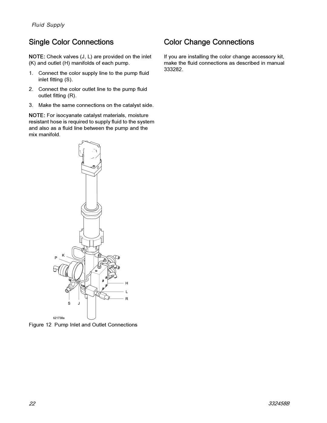
NOTE: Check valves (J, L) are provided on the inlet
(K) and outlet (H) manifolds of each pump.
1.Connect the color supply line to the pump fluid inlet fitting (S).
2.Connect the color outlet line to the pump fluid outlet fitting (R).
3.Make the same connections on the catalyst side.
NOTE: For isocyanate catalyst materials, moisture resistant hose is required to supply fluid to the system and also as a fluid line between the pump and the mix manifold.
Figure 12 Pump Inlet and Outlet Connections
Color Change Connections
If you are installing the color change accessory kit, make the fluid connections as described in manual 333282.
22 | 332458B |
