Electrical Supply
Improper wiring may cause electric shock or other serious injury if work is not performed properly. All electrical wiring must be completed by a qualified electrician and comply with all local codes and regulations.
Electrical Requirements
Enclose all cables routed in the spray booth and high traffic areas in conduit to prevent damage from paint, solvent, and traffic.
The unit operates with
•A power supply cord compatible to your local power configuration is not included. Wire gauge size must be
•The input power access port is 22.4 mm (0.88 in.) in diameter. A strain relief is provided which accepts a cord diameter of
Electrical Supply
Electrical Connections
See Electrical Schematics, page 29.
1.Verify that electrical power at the main panel is shut off. Open the Control Box cover.
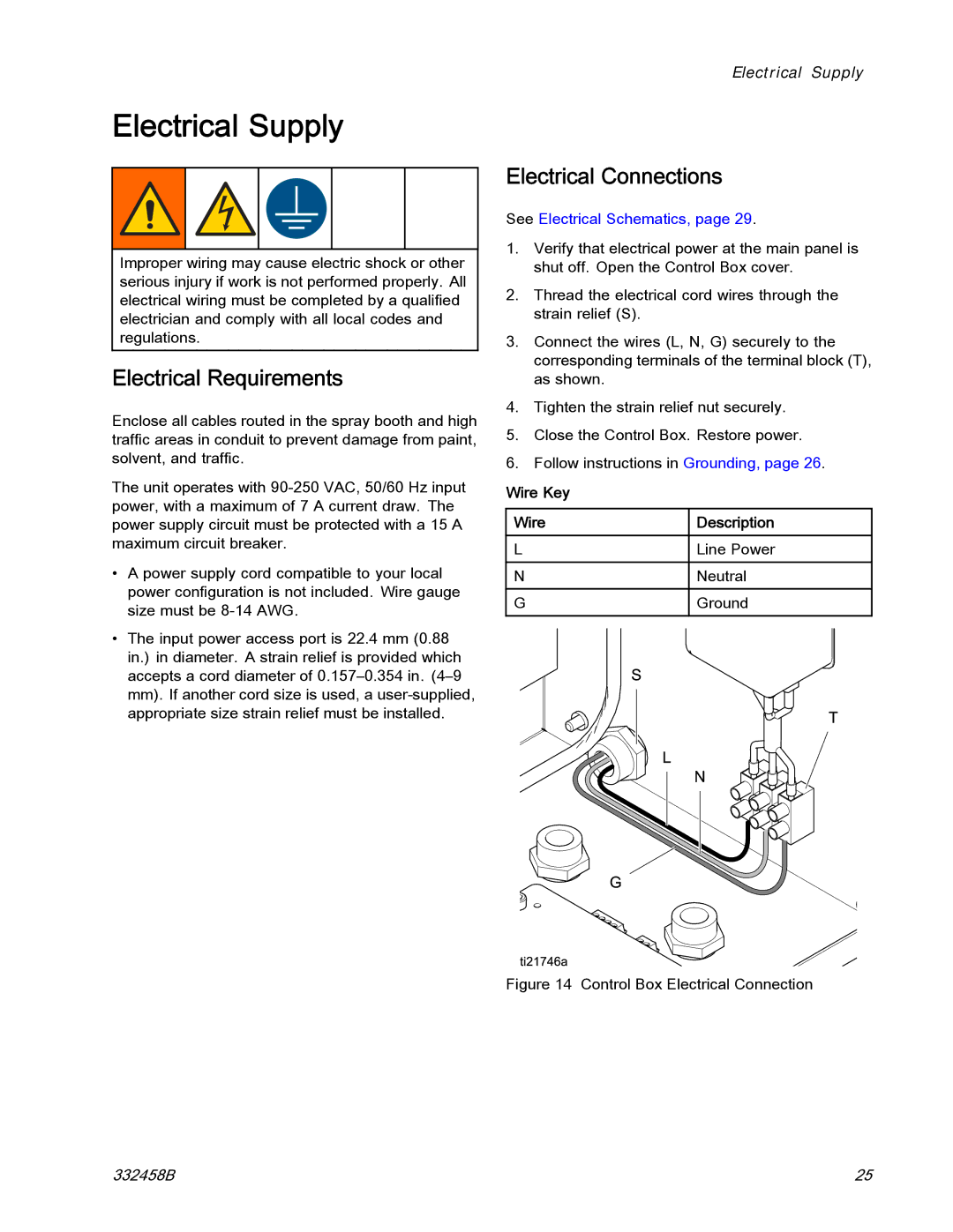
2.Thread the electrical cord wires through the strain relief (S).
3.Connect the wires (L, N, G) securely to the corresponding terminals of the terminal block (T), as shown.
4.Tighten the strain relief nut securely.
5.Close the Control Box. Restore power.
6.Follow instructions in Grounding, page 26.
Wire Key |
|
| |
| Wire |
| Description |
|
| ||
| L |
| Line Power |
| N |
| Neutral |
| G |
| Ground |
|
|
|
|
Figure 14 Control Box Electrical Connection
332458B | 25 |