Component Identification
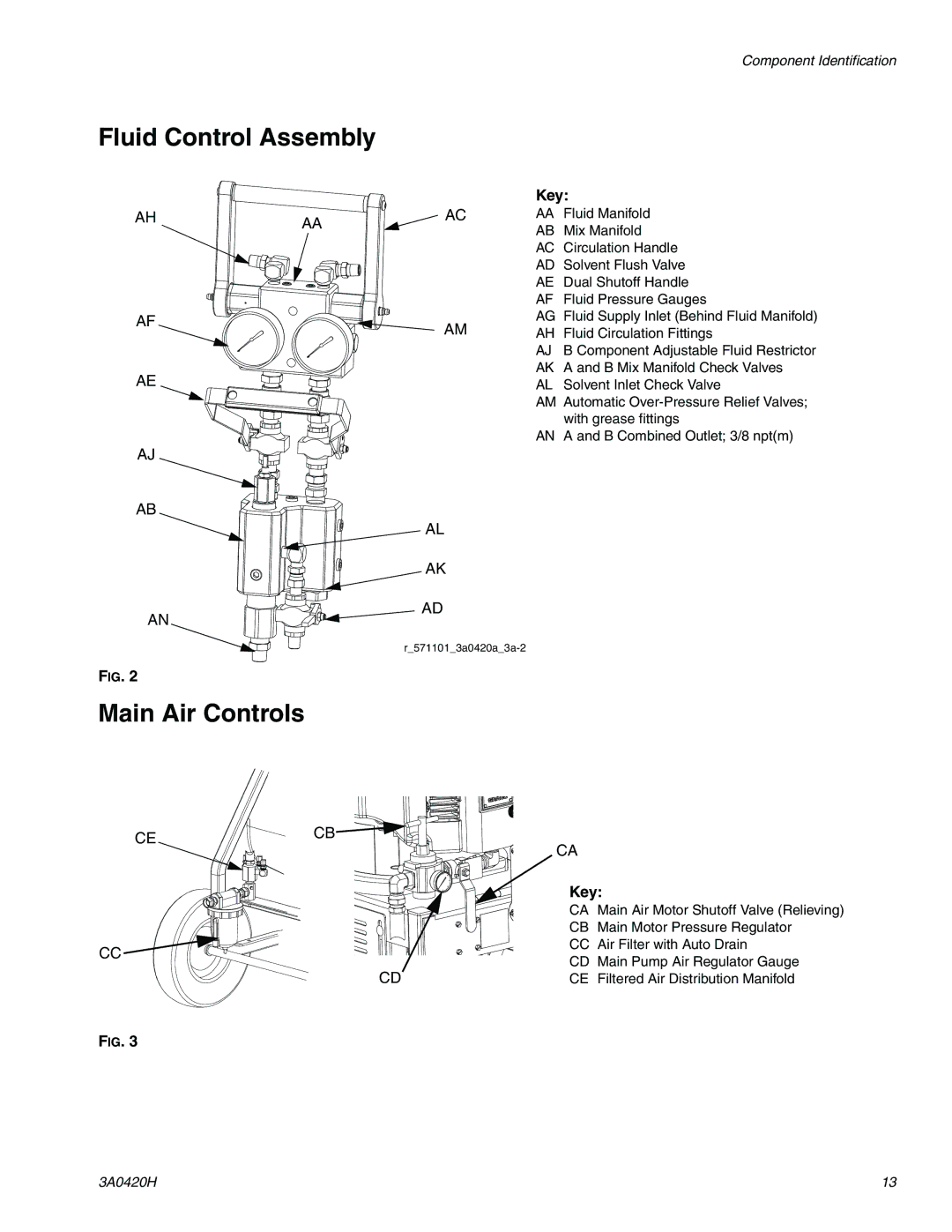
Fluid Control Assembly
AH | AA | AC |
|
|
AF | AM |
| |
AE |
|
AJ
AB
AL
AK
AD
AN
FIG. 2
Key:
AAFluid Manifold AB Mix Manifold
AC Circulation Handle AD Solvent Flush Valve AE Dual Shutoff Handle AF Fluid Pressure Gauges
AG Fluid Supply Inlet (Behind Fluid Manifold) AH Fluid Circulation Fittings
AJ B Component Adjustable Fluid Restrictor AK A and B Mix Manifold Check Valves
AL Solvent Inlet Check Valve
AM Automatic
AN A and B Combined Outlet; 3/8 npt(m)
Main Air Controls
CE | CB | CA |
|
|
| ||
|
|
| |
|
| Key: | |
|
| CA | Main Air Motor Shutoff Valve (Relieving) |
|
| CB | Main Motor Pressure Regulator |
CC |
| CC | Air Filter with Auto Drain |
| CD Main Pump Air Regulator Gauge | ||
| CD | ||
| CE | Filtered Air Distribution Manifold | |
FIG. 3
3A0420H | 13 |