Contents
GMaxr 3900, 5900, 5900HD Airless Paint Sprayers
Important Safety Instructions
INSTRUCTIONS-REPAIR309409E
GRACO INC. P.O. BOX 1441 MINNEAPOLIS, MN
Caution Symbol
Table of Contents
Warning Symbol
Warnings and Cautions
RECOIL HAZARD
INJECTION HAZARD
TOXIC FLUID HAZARD
309409
EQUIPMENT MISUSE HAZARD
HAZARD OF USING FLUIDS CONTAINING HALOGENATED HYDROCARBONS
FIRE AND EXPLOSION HAZARD
INJECTION HAZARD
Maintenance
Pressure Relief Procedure
AFTER THE FIRST 20 HOURS OF OPERATION
SOLUTION
Troubleshooting
PROBLEM
CAUSE
Use larger diameter hose and/or reduce overall
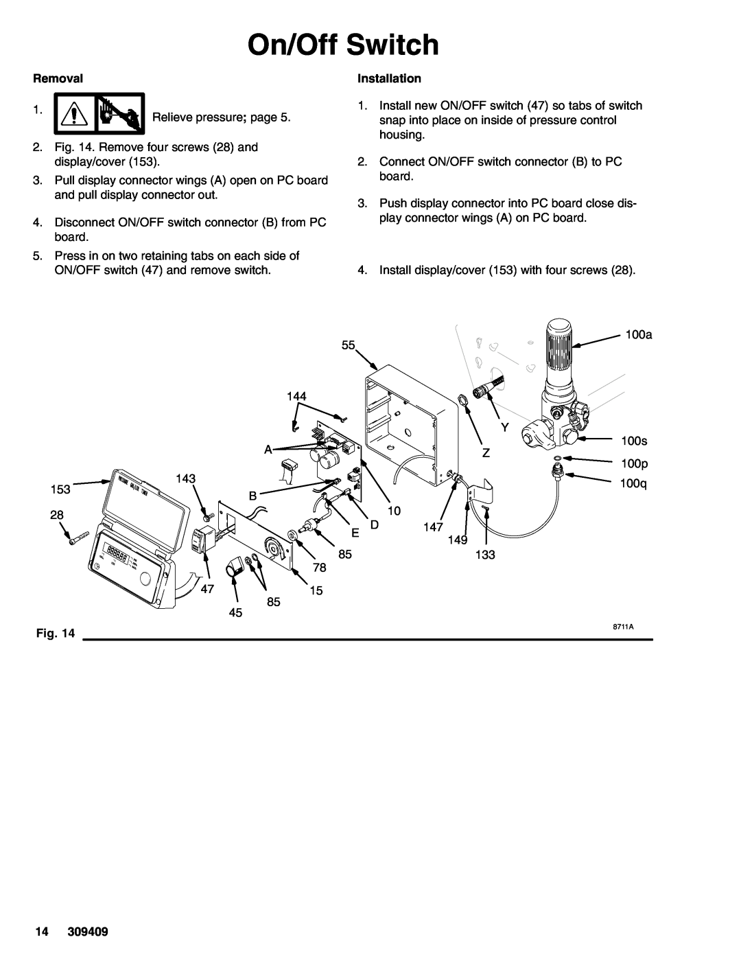
Removal
Bearing Housing and Connecting Rod
Installation
Model 233701 shown
Secure gallon counting sensor wire to clutch wire with a tie wrap
Drive Housing
Cut tie wrap holding gallon counting sensor wire to clutch wire
8699A
Pinion Assembly/Rotor/Field/Shaft/Clutch
Bottom View
10. Remove four screws 16 and lockwashers 11. Remove armature 4a 4a
7. Fig. 7. Remove retaining ring 19e
8. Tap pinion shaft 19d out with plastic mallet 19e 19d
8703B
Clamp
Clutch Housing
Engine
On/Off Switch
8711A
Control Board
Pressure Adjust Potentiometer
Pressure Control
Pressure Control Transducer
Digital Display Messages
After a fault, follow these steps to restart sprayer
Pressure Control Repair
DISPLAY
Removal
Displacement Pump
Installation
Repair
Parts Drawing - GMax 3900, 5900, 5900HD Hi-Boy Sprayers
Models 233701, 233706 and
Ref No. Part No
Parts List - GMax 3900, 5900, 5900HD Hi-Boy Sprayers
Y Danger & Warning labels, tags, and cards are free
Description
Parts List & Drawing - Pinion Assembly
Ref No. 19 and
309409
Parts Drawing - GMax 3900 and GMax 5900 Lo-Boy Sprayers
Models 233700 and
Parts List - GMax 3900 and GMax 5900 Lo-Boy Sprayers
Models 233706 through 233708 233716 and
Parts Drawing - Sprayer
GMax 3900, 5900 and 5900HD Sprayers Models 233700 through
VIEW A
Parts List - Sprayer
Pressure Control Wiring Diagram
Models 233700 through 233703 233705 through 233707 233716 and
Displacement Pump Repair Kits
Parts List/Drawing - Sprayers with RAC Tip, Gun & Hose
Accessories
Models 233702, 233703, 233707, 233708
GMax
Technical Data
Dimensions
Model 233701
FOR GRACO CANADA CUSTOMERS
Graco Warranty
ADDITIONAL WARRANTY COVERAGE
Graco reserves the right to make changes at any time without notice