Service
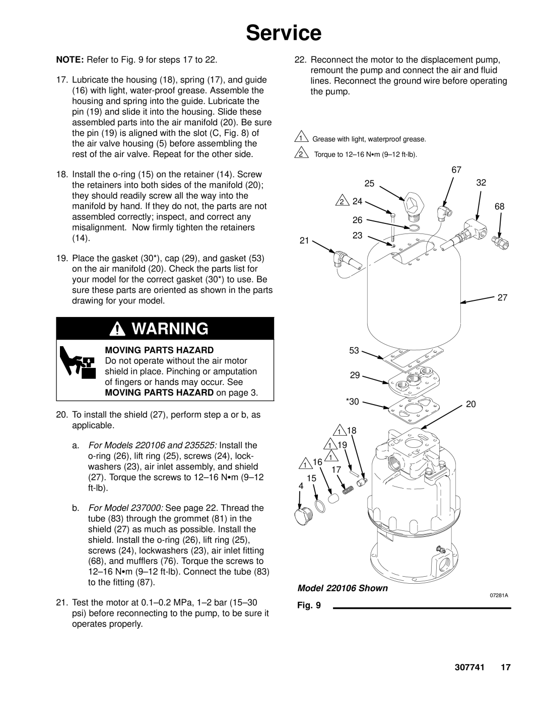
NOTE: Refer to Fig. 9 for steps 17 to 22.
17. Lubricate the housing (18), spring (17), and guide |
(16) with light, |
housing and spring into the guide. Lubricate the |
pin (19) and slide it into the housing. Slide these |
assembled parts into the air manifold (20). Be sure |
the pin (19) is aligned with the slot (C, Fig. 8) of |
the air valve housing (5) before assembling the |
rest of the air valve. Repeat for the other side. |
18. Install the |
the retainers into both sides of the manifold (20); |
they should readily screw all the way into the |
manifold by hand. If they do not, the parts are not |
assembled correctly; inspect, and correct any |
22.Reconnect the motor to the displacement pump, remount the pump and connect the air and fluid lines. Reconnect the ground wire before operating the pump.
1Grease with light, waterproof grease.
2Torque to
| 67 |
25 | 32 |
2 24
68
misalignment. Now firmly tighten the retainers |
(14). |
19. Place the gasket (30*), cap (29), and gasket (53) |
on the air manifold (20). Check the parts list for |
your model for the correct gasket (30*) to use. Be |
sure these parts are oriented as shown in the parts |
drawing for your model. |
21
26 ![]()
23
27
![]() WARNING
WARNING
MOVING PARTS HAZARD
Do not operate without the air motor shield in place. Pinching or amputation of fingers or hands may occur. See MOVING PARTS HAZARD on page 3.
20.To install the shield (27), perform step a or b, as applicable.
a.For Models 220106 and 235525: Install the
b.For Model 237000: See page 22. Thread the tube (83) through the grommet (81) in the shield (27) as much as possible. Install the shield. Install the
21.Test the motor at
53
29
*30 | 20 |
|
1 18
119
116 1
17
15
4
Model 220106 Shown
07281A
Fig. 9
307741 17