Air Line
1.Install an air filter (A) on the gun air line to ensure a dry, clean air supply to the gun. Dirt and moisture can ruin the appearance of your finished workpiece. See FIG. 1.
2.Install an air pressure regulator (C) on the gun air line to control air pressure to the gun.
3.Install an air shutoff valve (B) on the gun air line and on the pump air line, to shut off air to the gun.
4.Use a 3/16 in. (5 mm) I.D. or larger air hose to mini- mize excessive pressure drop in the hose.
![]() The gun air inlet has a
The gun air inlet has a
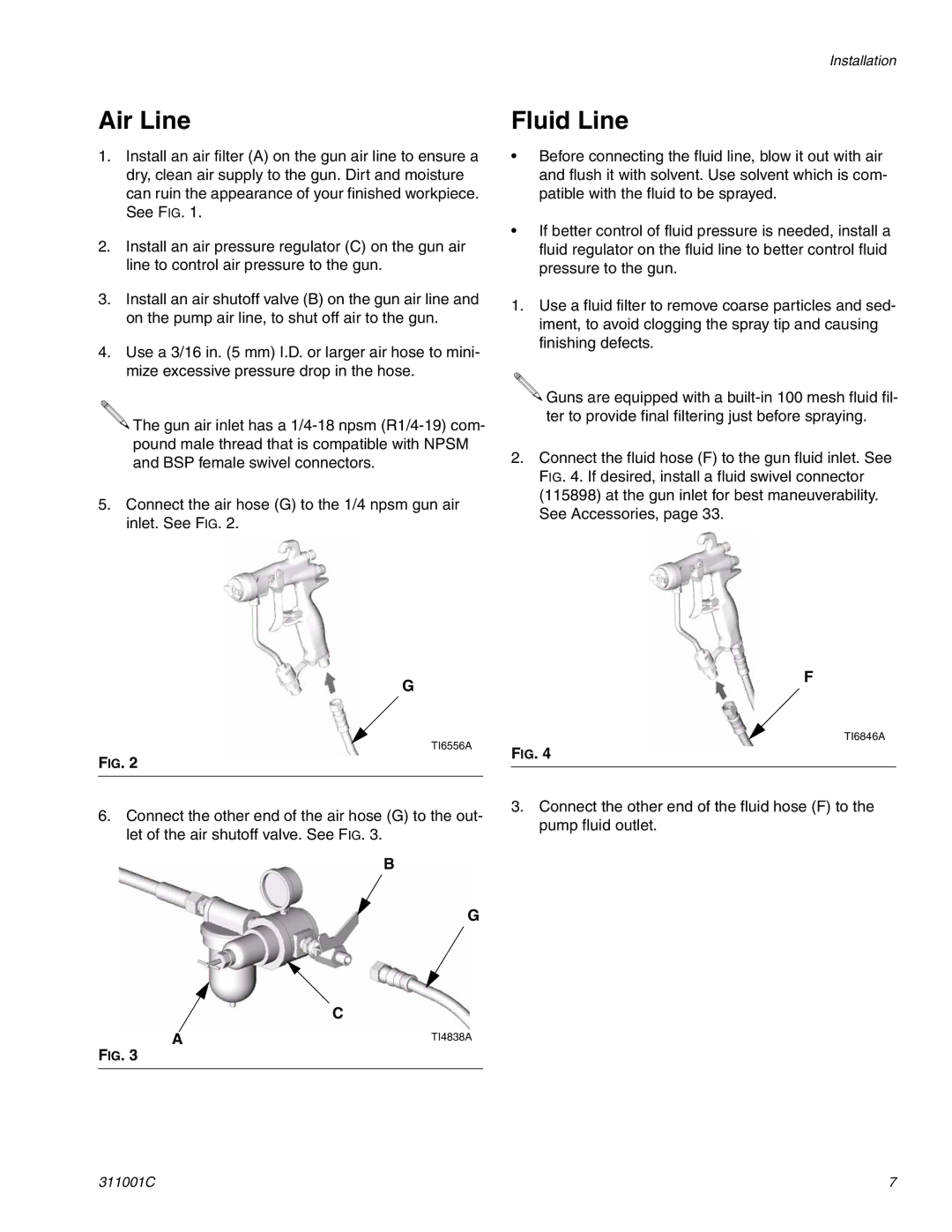
5.Connect the air hose (G) to the 1/4 npsm gun air inlet. See FIG. 2.
G
TI6556A
FIG. 2
Installation
Fluid Line
•Before connecting the fluid line, blow it out with air and flush it with solvent. Use solvent which is com- patible with the fluid to be sprayed.
•If better control of fluid pressure is needed, install a fluid regulator on the fluid line to better control fluid pressure to the gun.
1.Use a fluid filter to remove coarse particles and sed- iment, to avoid clogging the spray tip and causing finishing defects.
![]() Guns are equipped with a
Guns are equipped with a
ter to provide final filtering just before spraying.
2.Connect the fluid hose (F) to the gun fluid inlet. See FIG. 4. If desired, install a fluid swivel connector (115898) at the gun inlet for best maneuverability. See Accessories, page 33.
F
TI6846A
FIG. 4
6.Connect the other end of the air hose (G) to the out- let of the air shutoff valve. See FIG. 3.
B
G
C
A | TI4838A |
FIG. 3
3.Connect the other end of the fluid hose (F) to the pump fluid outlet.
311001C | 7 |