optional accessories

Wiring Diagram

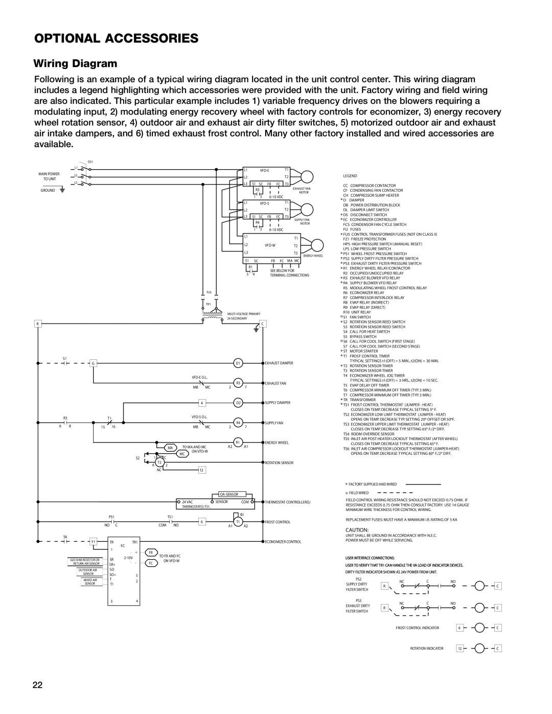
Following is an example of a typical wiring diagram located in the unit control center.. This wiring diagram includes a legend highlighting which accessories were provided with the unit.. Factory wiring and field wiring are also indicated.. This particular example includes 1) variable frequency drives on the blowers requiring a modulating input, 2) modulating energy recovery wheel with factory controls for economizer, 3) energy recovery wheel rotation sensor, 4) outdoor air and exhaust air dirty filter switches, 5) motorized outdoor air and exhaust air intake dampers, and 6) timed exhaust frost control.. Many other factory installed and wired accessories are available..

DS1

L1

MAIN POWER


L2


TO UNIT


L3


GROUND


R

S1

G


L1


VFD-E


T1


L2


T2


L3


S1


SC

FR

FC

T3


R3


EXHAUST FAN


3


MOTOR


L1

1


0-10 VDC

T1


VFD-S


L2


T2


L3


S1


SC

FR

FC

T3


R4


SUPPLY FAN


MOTOR


1


3

0-10 VDC


L1


T1


L2


VFD-W


T2


L3


T3


ENERGY WHEEL


S1


SC

FR

FC

MA MC


R1


SEE BELOW FOR


3


4


TERMINAL CONNECTIONS

FU5

TR1

MULTI-VOLTAGE PRIMARY 24 SECONDARY

C

D1

EXHAUST DAMPER

VFD-E O.L.

LEGEND

CC COMPRESSOR CONTACTOR

CF CONDENSING FAN CONTACTOR

CH COMPRESSOR SUMP HEATER

*D DAMPER

DB POWER DISTRIBUTION BLOCK DL DAMPER LIMIT SWITCH

*DS DISCONNECT SWITCH

*EC ECONOMIZER CONTROLLER

FCS CONDENSOR FAN CYCLE SWITCH FU FUSES

*FU5 CONTROL TRANSFORMER FUSES (NOT ON CLASS II) FZ1 FREEZE PROTECTION

HPS HIGH PRESSURE SWITCH (MANUAL RESET) LPS LOW PRESSURE SWITCH

*PS1 WHEEL FROST PRESSURE SWITCH

*PS2 SUPPLY DIRTY FILTER PRESSURE SWITCH

*PS3 EXHAUST DIRTY FILTER PRESSURE SWITCH

*R1 ENERGY WHEEL RELAY/CONTACTOR

R2 OCCUPIED/UNOCCUPIED RELAY

*R3 EXHAUST BLOWER VFD RELAY

*R4 SUPPLY BLOWER VFD RELAY

R5 MODULATING WHEEL FROST CONTROL RELAY

R6 ECONOMIZER RELAY

R7 COMPRESSOR INTERLOCK RELAY

R8 EVAP RELAY (INDIRECT)

R9 EVAP RELAY (DIRECT)

R10 UNIT RELAY

o S1 FAN SWITCH

*S2 ROTATION SENSOR REED SWITCH

S3 ROTATION SENSOR REED SWITCH

S4 CALL FOR HEAT SWITCH

S5 BYPASS SWITCH

oS6 CALL FOR COOL SWITCH (FIRST STAGE)

S7 CALL FOR COOL SWITCH (SECOND STAGE)

*ST MOTOR STARTER

*T1 FROST CONTROL TIMER

TYPICAL SETTINGS t1(OFF) = 5 MIN., t2(ON) = 30 MIN.

* T2

ROTATION SENSOR TIMER

T3

ROTATION SENSOR TIMER

T4

ECONOMIZER WHEEL JOG TIMER


TYPICAL SETTINGS t1(OFF) = 3 HRS., t2(ON) = 10 SEC.

R3T1

6


8


15

16


R3

EXHAUST FAN


MB

MC

2

7


4

D2

SUPPLY DAMPER


VFD-S O.L.


R4

SUPPLY FAN


MB

MC

2

7


R1

ENERGY WHEEL


MA

TO MA AND MC

A2

A1


MC

ON VFD-W


S2

1

C


6 T2

2


ROTATION SENSOR


NC


12


T5

EVAP DELAY OFF TIMER

T6

COMPRESSOR MINIMUM OFF TIMER (TYP. 3 MIN.)

T7

COMPRESSOR MINIMUM OFF TIMER (TYP. 3 MIN.)

* TR

TRANSFORMER

* TS1 FROST CONTROL THERMOSTAT (JUMPER - HEAT)


CLOSES ON TEMP. DECREASE TYPICAL SETTING 5º F.

TS2 ECONOMIZER LOW LIMIT THERMOSTAT (JUMPER - HEAT) OPENS ON TEMP. DECREASE TYP. SETTING 20º OFFSET OR 50ºF.

TS3 ECONOMIZER UPPER LIMIT THERMOSTAT (JUMPER - HEAT) CLOSES ON TEMP. DECREASE TYP. SETTING 65º F./2º DIFF.

TS4 ROOM OVERRIDE SENSOR

TS5 INLET AIR POST HEATER LOCKOUT THERMOSTAT (AFTER WHEEL) CLOSES ON TEMP. DECREASE TYPICAL SETTING 65º F.

TS6 INLET AIR COMPRESSOR LOCKOUT THERMOSTAT (JUMPER-HEAT)

OPENS ON TEMP. DECREASE TYPICAL SETTING 60º F./2º DIFF.

*FACTORY SUPPLIED AND WIRED

OA-SENSOR

o FIELD WIRED

S6

Y1

620 OHM RESISTOR OR RETURN AIR SENSOR

OUTDOOR AIR

SENSOR

MIXED AIR

SENSOR


24 VAC

SENSOR

COM

THERMOSTAT CONTROLLER(S)


THERMOSTAT(S) TS1,


PS1


TS1


B1


6

T1


FROST CONTROL

NO C


COM

NO

A1

A2


TR

TR1


ECONOMIZER CONTROL

1

EC


+

FR


TO FR AND FC


SR

2-10V


ON VFD-W


-

FC


SR+


SO


SO+

5


T2

T1

FIELD CONTROL WIRING RESISTANCE SHOULD NOT EXCEED 0.75 OHM. IF RESISTANCE EXCEEDS 0.75 OHM THEN CONSULT FACTORY. USE 14 GAUGE MINIMUM WIRE THICKNESS FOR CONTROL WIRING.

REPLACEMENT FUSES: MUST HAVE A MINIMUM I.R. RATING OF 5 KA

CAUTION:

UNIT SHALL BE GROUND IN ACCORDANCE WITH N.E.C.

POWER MUST BE OFF WHILE SERVICING.

USER INTERFACE CONNECTIONS:

USER TO VERIFY THAT TR1 CAN HANDLE THE VA LOAD OF INDICATOR DEVICES.

DIRTY FILTER INDICATOR SHOWN AS 24V POWER FROM UNIT.

PS2

NC

C

NO

SUPPLY DIRTY

R


FILTER SWITCH


C

34

PS3

EXHAUST DIRTYNCCNO R

FILTER SWITCH

C

FROST CONTROL INDICATOR

6

C

ROTATION INDICATOR

12

C

22

Page 22
Image 22
Greenheck Fan 55, HRE-20, 90, 45 manual Wiring Diagram, Transformer

45, 55, 90, HRE-20 specifications

The Greenheck Fan HRE series, specifically the models HRE-20, HRE-90, HRE-55, and HRE-45, represents a blend of innovation and efficiency in the HVAC industry. Built for both commercial and industrial applications, these exhaust fans stand out due to their robust design and advanced operational features.

One of the main features of the HRE series is its energy-efficient motor design. These fans come equipped with a premium efficiency motor that reduces energy consumption while maintaining high performance. The motors are specifically designed to provide exceptional airflow while operating at lower sound levels, ensuring a quieter environment.

The HRE models also showcase advanced aerodynamic design, featuring optimized blade geometry that enhances airflow performance. This design ensures that the fans can deliver consistent and effective air movement even at varying operational conditions. This makes the HRE series suitable for use in a wide range of applications, from commercial kitchens to industrial processes.

Another significant characteristic of the HRE series is its durability. Constructed from high-quality materials, these fans are built to withstand harsh environmental conditions and prolonged usage. The robust casing and corrosion-resistant finishes ensure longevity, reducing the need for frequent repairs or replacements.

In terms of installation and maintenance, the HRE series offers significant advantages. The fans are designed for easy installation with clear mounting instructions. Additionally, maintenance procedures are simplified, allowing for hassle-free access to critical components, which reduces downtime and operating costs.

Technologically, the HRE models incorporate advanced controls and monitoring systems. These systems can offer real-time feedback on operational performance, allowing for proactive maintenance and energy management. Integrated controls can be customized to work with building management systems, providing users with seamless integration and control capabilities.

Overall, the Greenheck Fan HRE-20, HRE-90, HRE-55, and HRE-45 exemplify a commitment to quality and efficiency in commercial and industrial ventilation solutions. Their combination of energy efficiency, advanced design, durability, and user-friendly features make them a leading choice for those seeking reliable airflow solutions. These fans not only meet current industry standards but also set a benchmark for performance and innovation in the HVAC sector.