Installation Instructions for:
NV-45 w/Downblast Discharge
Before beginning this installation:
Make sure that there is room to access the unit from all sides. Make sure inlet of unit is located well away from any exhaust fans.
Step 1 Roof Opening
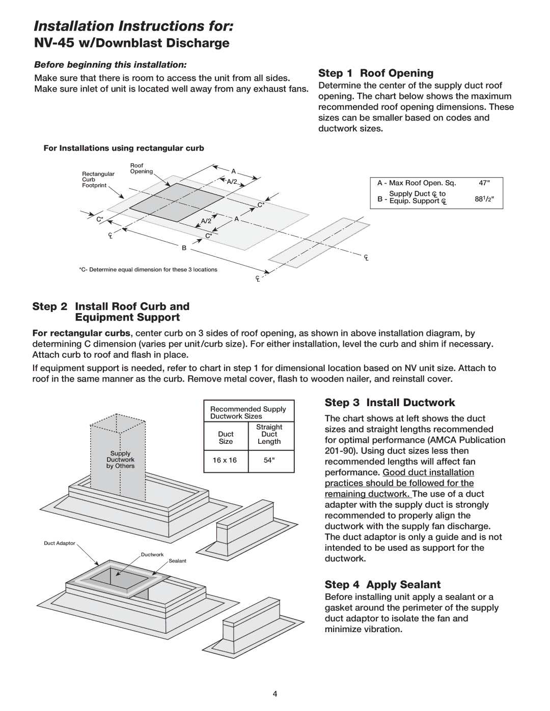
Determine the center of the supply duct roof opening. The chart below shows the maximum recommended roof opening dimensions. These sizes can be smaller based on codes and ductwork sizes.
For Installations using rectangular curb
| Roof |
| A |
Rectangular | Opening |
| |
Curb |
|
| A/2 |
Footprint |
|
| |
|
|
| |
|
|
| C* |
C* |
| A/2 | A |
C |
| C* |
|
L |
|
|
B
C
L
*C- Determine equal dimension for these 3 locations
C
L
A - Max Roof Open. Sq. | 47" |
Supply Duct C to |
|
L | 881/2" |
B - Equip. Support C | |
L |
|
Step 2 Install Roof Curb and
Equipment Support
For rectangular curbs, center curb on 3 sides of roof opening, as shown in above installation diagram, by determining C dimension (varies per unit/curb size). For either installation, level the curb and shim if necessary. Attach curb to roof and flash in place.
If equipment support is needed, refer to chart in step 1 for dimensional location based on NV unit size. Attach to roof in the same manner as the curb. Remove metal cover, flash to wooden nailer, and reinstall cover.
|
| Recommended Supply | |
|
| Ductwork Sizes | |
|
|
|
|
|
|
| Straight |
|
| Duct | Duct |
|
| Size | Length |
|
|
|
|
Supply |
| 16 x 16 | 54" |
Ductwork |
| ||
by Others |
|
|
|
|
|
|
|
Duct Adaptor
Ductwork
Sealant
Step 3 Install Ductwork
The chart shows at left shows the duct sizes and straight lengths recommended for optimal performance (AMCA Publication
Step 4 Apply Sealant
Before installing unit apply a sealant or a gasket around the perimeter of the supply duct adaptor to isolate the fan and minimize vibration.
4