Table of Contents

Installation

Filter/Stand Section . . . . . . . . . . . .3-4 Burner/Blower Section. . . . . . . . . . . 4 Ductwork. . . . . . . . . . . . . . . . . 4 Dimensional Data . . . . . . . . . . . . . 5 Direct Gas Piping . . . . . . . . . . . . .6-7

Start-Up

Blower. . . . . . . . . . . . . . . . . 8-9 Direct Gas. . . . . . . . . . . . . . .10-12

Operation

Electrical . . . . . . . . . . . . . . . . 13

Troubleshooting

Blower. . . . . . . . . . . . . . . . . 14 Heater . . . . . . . . . . . . . . . . 15-17

Maintenance

Routine . . . . . . . . . . . . . . . .18-19 Fall. . . . . . . . . . . . . . . . . . . 19

Reference

Typical Control Center Layout. . . . . . . . 20 Typical Gas Train Layout. . . . . . . . . . 20 Start-Up Check List . . . . . . . . . . . . 21 Maintenance Log . . . . . . . . . . . .22-23 Warranty . . . . . . . . . . . . . Backcover

Installation

1. Filter/Stand Section

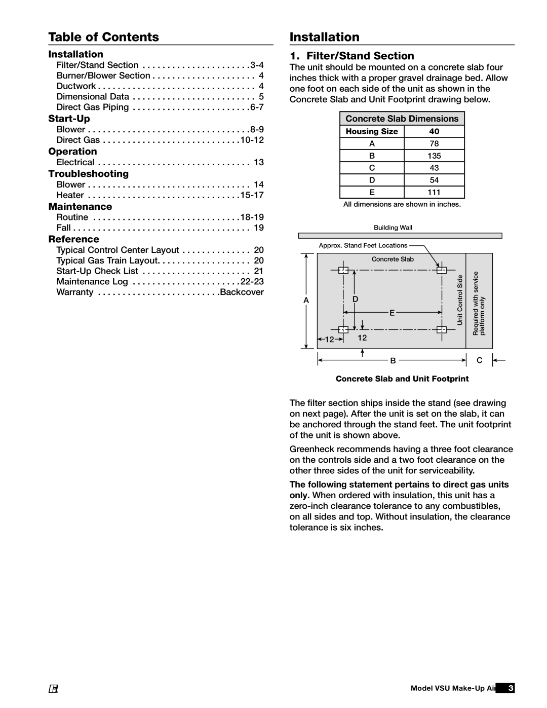
The unit should be mounted on a concrete slab four inches thick with a proper gravel drainage bed. Allow one foot on each side of the unit as shown in the Concrete Slab and Unit Footprint drawing below.

Concrete Slab Dimensions

Housing Size

40

A

78

B

135


C

43


D

54


E

111


All dimensions are shown in inches.

Building Wall

Approx. Stand Feet Locations


Concrete Slab


ControlUnitSide

withRequiredservice onlyplatform


A


D


E


12


12


B C

Concrete Slab and Unit Footprint

The filter section ships inside the stand (see drawing on next page). After the unit is set on the slab, it can be anchored through the stand feet. The unit footprint of the unit is shown above.

Greenheck recommends having a three foot clearance on the controls side and a two foot clearance on the other three sides of the unit for serviceability.

The following statement pertains to direct gas units only. When ordered with insulation, this unit has a zero-inch clearance tolerance to any combustibles, on all sides and top. Without insulation, the clearance tolerance is six inches.

Model VSU Make-Up Air 3

®

Page 3
Image 3
Greenheck Fan VSU manual Table of Contents, Installation

VSU specifications

Greenheck Fan VSU, or Variable Speed Unit ventilators, represent a significant advancement in the field of HVAC technology. Designed to enhance air quality and energy efficiency, these units are particularly suited for commercial applications such as schools, offices, and industrial facilities. They provide a reliable solution for both heating and cooling, ensuring optimal comfort and productivity in diverse environments.

One of the hallmark features of the VSU is its variable speed motor. This innovation allows the fan speed to adjust according to the specific demands of the space, leading to substantial energy savings compared to traditional fixed-speed units. By operating at reduced speeds during lower load conditions, the VSU minimizes energy consumption while maintaining comfortable indoor conditions. This adaptive capability not only lowers utility bills but also contributes to a reduced environmental footprint.

In addition to energy efficiency, the VSU is equipped with advanced controls that provide precise temperature management and air distribution. These controls can be integrated into existing building management systems, giving facility managers the ability to monitor and fine-tune operations remotely. The ability to set specific schedules and program temperature settings enhances overall building performance and ensures that spaces are only conditioned when necessary.

The VSU is designed with a robust and durable construction, featuring corrosion-resistant materials that prolong the unit's lifespan. This reliability is further enhanced by its easy accessibility for maintenance, making it a cost-effective solution for long-term use. Users can expect a quiet operation due to the fan’s advanced design, which significantly reduces noise levels compared to traditional models.

Furthermore, the VSU supports a variety of custom configurations, allowing it to meet the specific needs of different applications. Whether it's integrating with other HVAC components or adapting to varied ceiling heights, the flexibility of the Greenheck Fan VSU makes it a versatile choice for engineers and building owners alike.

In conclusion, the Greenheck Fan VSU stands out for its combination of energy efficiency, advanced control options, durability, and adaptability. As the demand for sustainable and effective HVAC solutions continues to grow, the VSU positions itself as a top choice for those seeking to enhance indoor air quality while minimizing operational costs.