4. Set the Maximum Firing Rate

Monitor the unit’s actual temperature rise by placing a thermocouple in the unit’s inlet and a second in the discharge, three duct diameters downstream of the burner.

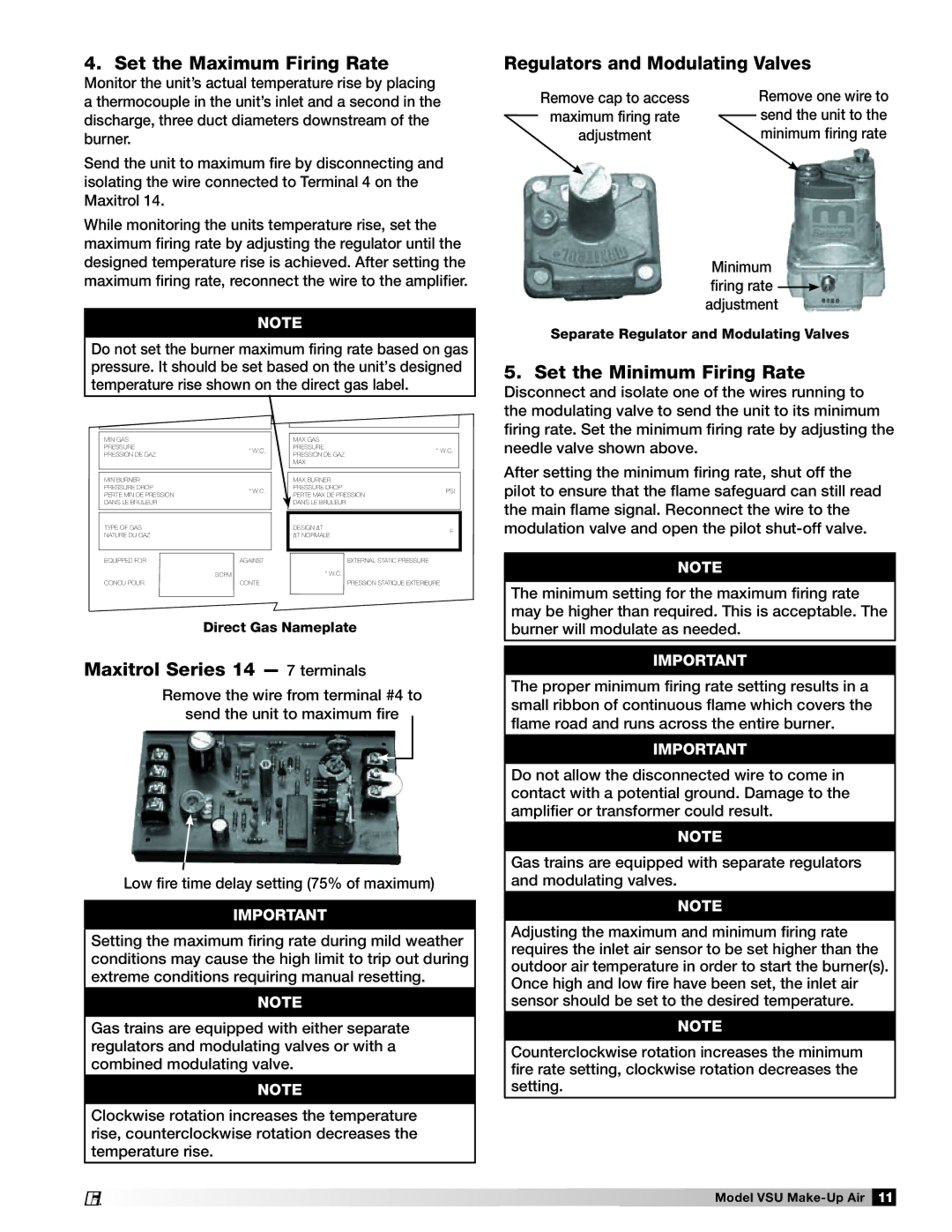
Send the unit to maximum fire by disconnecting and isolating the wire connected to Terminal 4 on the Maxitrol 14.

While monitoring the units temperature rise, set the maximum firing rate by adjusting the regulator until the designed temperature rise is achieved. After setting the maximum firing rate, reconnect the wire to the amplifier.

note

Do not set the burner maximum firing rate based on gas pressure. It should be set based on the unit’s designed temperature rise shown on the direct gas label.

Regulators and Modulating Valves

Remove cap to access


Remove one wire to

maximum firing rate


send the unit to the


adjustment


minimum firing rate

Minimum

firing rate adjustment

Separate Regulator and Modulating Valves

5. Set the Minimum Firing Rate

Disconnect and isolate one of the wires running to the modulating valve to send the unit to its minimum firing rate. Set the minimum firing rate by adjusting the

MIN GAS

PRESSURE“ W.C.

PRESSION DE GAZ

MIN BURNER

PRESSURE DROP“ W.C. PERTE MIN DE PRESSION

DANS LE BRULEUR

TYPE OF GAS

NATURE DU GAZ

EQUIPPED FOR

AGAINST


SCFM

CONCU POUR

CONTE

MAX GAS

PRESSURE“ W.C.

PRESSION DE GAZ MAX

MAX BURNER

PRESSURE DROPPSI PERTE MAX DE PRESSION

DANS LE BRULEUR

DESIGN ∆T

F

∆T NORMALE


EXTERNAL STATIC PRESSURE

“ W.C.


PRESSION STATIQUE EXTERIEURE

needle valve shown above.

After setting the minimum firing rate, shut off the pilot to ensure that the flame safeguard can still read the main flame signal. Reconnect the wire to the modulation valve and open the pilot shut-off valve.

note

The minimum setting for the maximum firing rate may be higher than required. This is acceptable. The

Direct Gas Nameplate

Maxitrol Series 14 — 7 terminals

Remove the wire from terminal #4 to

send the unit to maximum fire

Low fire time delay setting (75% of maximum)

Important

Setting the maximum firing rate during mild weather conditions may cause the high limit to trip out during extreme conditions requiring manual resetting.

note

Gas trains are equipped with either separate regulators and modulating valves or with a combined modulating valve.

note

Clockwise rotation increases the temperature rise, counterclockwise rotation decreases the temperature rise.

burner will modulate as needed.

IMPORTANT

The proper minimum firing rate setting results in a small ribbon of continuous flame which covers the flame road and runs across the entire burner.

Important

Do not allow the disconnected wire to come in contact with a potential ground. Damage to the amplifier or transformer could result.

NOTE

Gas trains are equipped with separate regulators and modulating valves.

NOTE

Adjusting the maximum and minimum firing rate requires the inlet air sensor to be set higher than the outdoor air temperature in order to start the burner(s). Once high and low fire have been set, the inlet air sensor should be set to the desired temperature.

NOTE

Counterclockwise rotation increases the minimum fire rate setting, clockwise rotation decreases the setting.

Model VSU Make-Up Air 11

®

Page 11
Image 11
Greenheck Fan VSU manual Set the Maximum Firing Rate, Regulators and Modulating Valves, Set the Minimum Firing Rate

VSU specifications

Greenheck Fan VSU, or Variable Speed Unit ventilators, represent a significant advancement in the field of HVAC technology. Designed to enhance air quality and energy efficiency, these units are particularly suited for commercial applications such as schools, offices, and industrial facilities. They provide a reliable solution for both heating and cooling, ensuring optimal comfort and productivity in diverse environments.

One of the hallmark features of the VSU is its variable speed motor. This innovation allows the fan speed to adjust according to the specific demands of the space, leading to substantial energy savings compared to traditional fixed-speed units. By operating at reduced speeds during lower load conditions, the VSU minimizes energy consumption while maintaining comfortable indoor conditions. This adaptive capability not only lowers utility bills but also contributes to a reduced environmental footprint.

In addition to energy efficiency, the VSU is equipped with advanced controls that provide precise temperature management and air distribution. These controls can be integrated into existing building management systems, giving facility managers the ability to monitor and fine-tune operations remotely. The ability to set specific schedules and program temperature settings enhances overall building performance and ensures that spaces are only conditioned when necessary.

The VSU is designed with a robust and durable construction, featuring corrosion-resistant materials that prolong the unit's lifespan. This reliability is further enhanced by its easy accessibility for maintenance, making it a cost-effective solution for long-term use. Users can expect a quiet operation due to the fan’s advanced design, which significantly reduces noise levels compared to traditional models.

Furthermore, the VSU supports a variety of custom configurations, allowing it to meet the specific needs of different applications. Whether it's integrating with other HVAC components or adapting to varied ceiling heights, the flexibility of the Greenheck Fan VSU makes it a versatile choice for engineers and building owners alike.

In conclusion, the Greenheck Fan VSU stands out for its combination of energy efficiency, advanced control options, durability, and adaptability. As the demand for sustainable and effective HVAC solutions continues to grow, the VSU positions itself as a top choice for those seeking to enhance indoor air quality while minimizing operational costs.