6.Raise the cutterhead assembly and remove the block of wood.
7.Repeat Steps
8.Replace the sides, top plates, and elevation crank.
Extension Wing/ Table Alignment
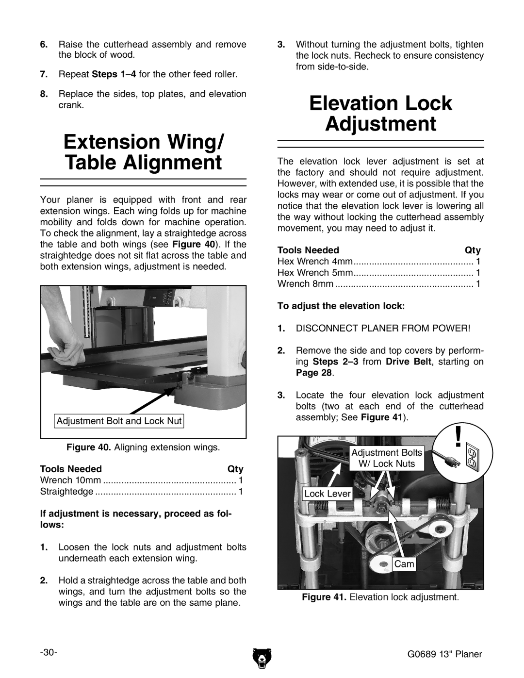
Your planer is equipped with front and rear extension wings. Each wing folds up for machine mobility and folds down for machine operation. To check the alignment, lay a straightedge across the table and both wings (see Figure 40). If the straightedge does not sit flat across the table and both extension wings, adjustment is needed.
Adjustment Bolt and Lock Nut
Figure 40. Aligning extension wings.
Tools Needed | Qty |
Wrench 10mm | 1 |
Straightedge | 1 |
If adjustment is necessary, proceed as fol- lows:
1.Loosen the lock nuts and adjustment bolts underneath each extension wing.
2.Hold a straightedge across the table and both wings, and turn the adjustment bolts so the wings and the table are on the same plane.
3.Without turning the adjustment bolts, tighten the lock nuts. Recheck to ensure consistency from
Elevation Lock
Adjustment
The elevation lock lever adjustment is set at the factory and should not require adjustment. However, with extended use, it is possible that the locks may wear or come out of adjustment. If you notice that the elevation lock lever is lowering all the way without locking the cutterhead assembly movement, you may need to adjust it.
Tools Needed | Qty |
Hex Wrench 4mm | 1 |
Hex Wrench 5mm | 1 |
Wrench 8mm | 1 |
To adjust the elevation lock: |
|
1.DISCONNECT PLANER FROM POWER!
2.Remove the side and top covers by perform- ing Steps
Page 28.
3.Locate the four elevation lock adjustment bolts (two at each end of the cutterhead assembly; See Figure 41).
Adjustment Bolts
W/ Lock Nuts
Lock Lever
Cam