G1024 specifications
The Grizzly G1024 is a powerful and versatile table saw that has earned a reputation among woodworkers for its reliability and precision. Designed for both amateur and professional use, it combines advanced technologies with user-friendly features, ensuring that it meets the demands of various woodworking projects.One of the standout features of the G1024 is its robust 1 HP motor. This motor delivers substantial power for cutting through various materials such as hardwood, softwood, and composite materials with ease. The saw is equipped with a 10-inch blade, which is standard in the industry and allows for a wide range of cuts, from rip cuts to crosscuts. The G1024 also supports a maximum cutting depth of 3-1/8 inches at 90 degrees and 2-1/4 inches at 45 degrees, making it versatile for different angles and thicknesses.
The G1024 incorporates a precision-ground cast-iron table, which provides stability and minimizes vibration during operation. The flat surface of the table ensures accurate cuts and is easy to maintain. The table size allows for extensive workpieces, with a generous extension table available for larger projects. In addition, the integrated T-slot miter gauge permits smooth movement of the gauge for precise angle cuts.
Safety is a priority in the design of the G1024. It comes with a blade guard that ensures protection against accidental contact with the spinning blade. The push stick and anti-kickback pawls further enhance user safety, allowing woodworkers to handle materials confidently without the fear of injury.
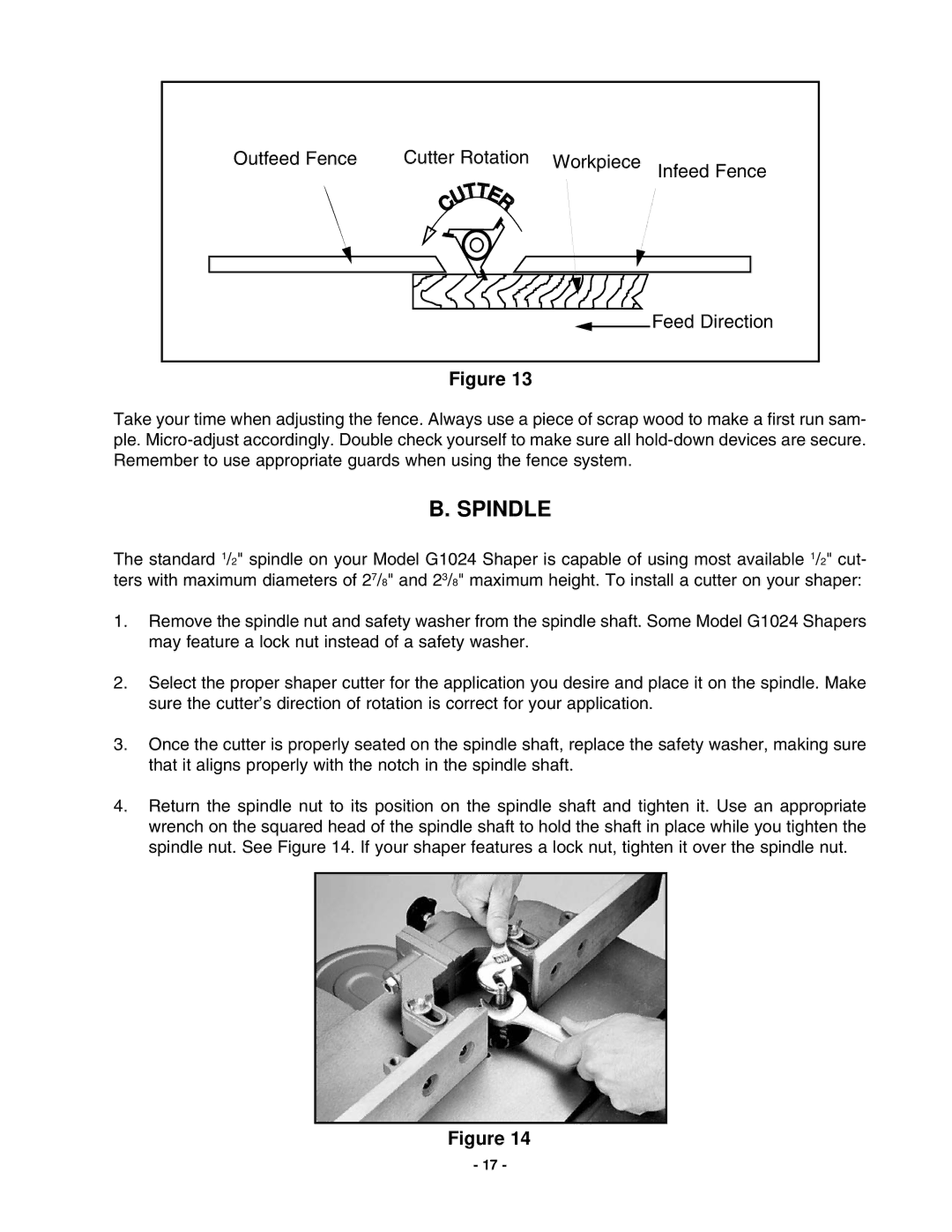
Another notable feature of the Grizzly G1024 is its fence system. The saw includes a reliable rip fence that locks securely in place, ensuring straight and accurate cuts every time. The fence’s easy adjustment mechanism allows for quick changes in width, making it an efficient tool for varying projects.
Overall, the Grizzly G1024 is designed to cater to woodworkers' needs, thanks to its blend of power, precision, and safety. Its advanced features make it suitable for a wide range of woodworking tasks, while its build quality ensures durability. Whether crafting furniture, cabinetry, or other wood projects, the G1024 stands as a dependable saw that enhances productivity and creativity in the workshop.

