Co-Planarity
1.Adjust the tracking knob (#23) so that upper wheel is not angled.
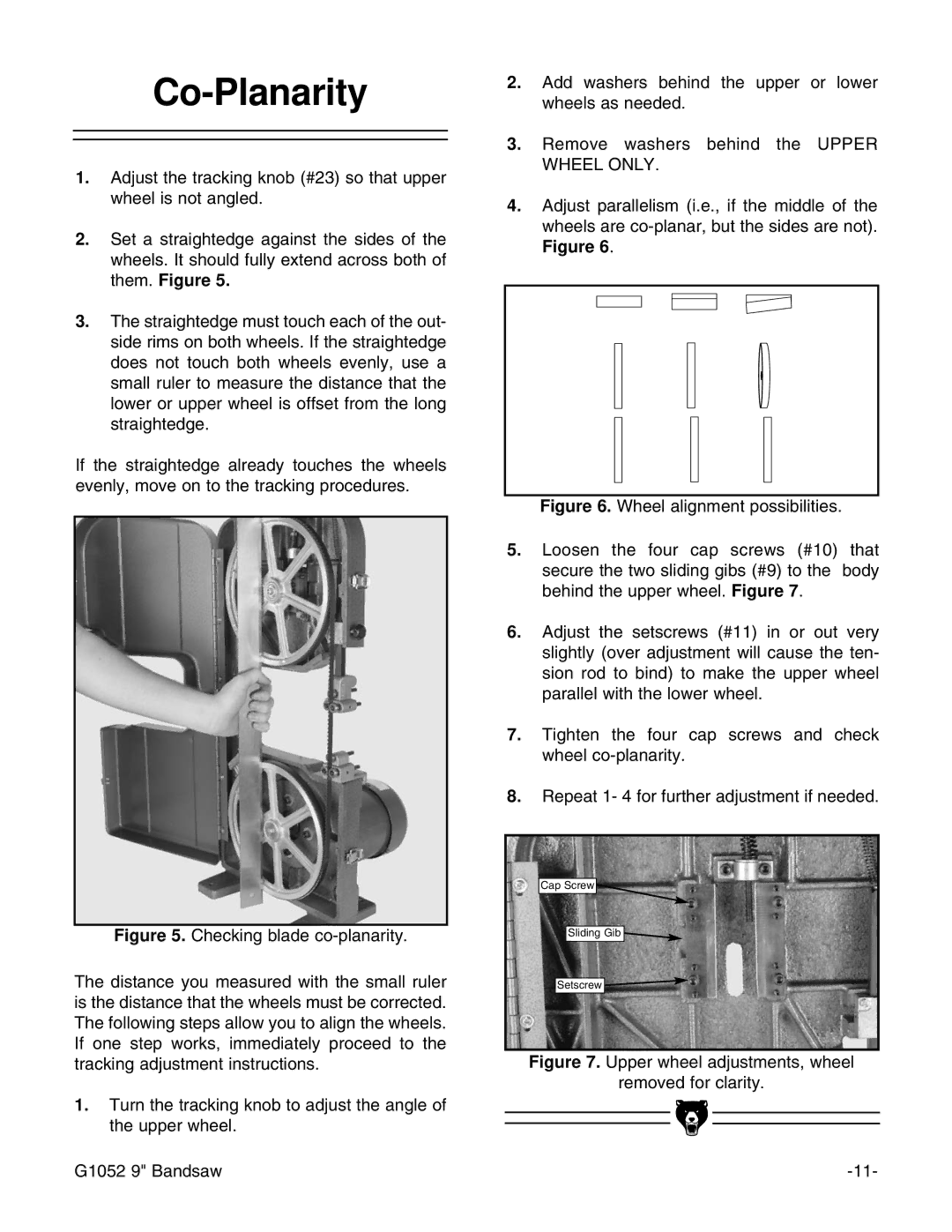
2.Set a straightedge against the sides of the wheels. It should fully extend across both of them. Figure 5.
3.The straightedge must touch each of the out- side rims on both wheels. If the straightedge does not touch both wheels evenly, use a small ruler to measure the distance that the lower or upper wheel is offset from the long straightedge.
If the straightedge already touches the wheels evenly, move on to the tracking procedures.
Figure 5. Checking blade co-planarity.
The distance you measured with the small ruler is the distance that the wheels must be corrected. The following steps allow you to align the wheels. If one step works, immediately proceed to the tracking adjustment instructions.
1.Turn the tracking knob to adjust the angle of the upper wheel.
2.Add washers behind the upper or lower wheels as needed.
3.Remove washers behind the UPPER WHEEL ONLY.
4.Adjust parallelism (i.e., if the middle of the wheels are co-planar, but the sides are not). Figure 6.
Figure 6. Wheel alignment possibilities.
5.Loosen the four cap screws (#10) that secure the two sliding gibs (#9) to the body behind the upper wheel. Figure 7.
6.Adjust the setscrews (#11) in or out very slightly (over adjustment will cause the ten- sion rod to bind) to make the upper wheel parallel with the lower wheel.
7.Tighten the four cap screws and check wheel co-planarity.
8.Repeat 1- 4 for further adjustment if needed.
Cap Screw ![]()
Sliding Gib ![]()
Setscrew ![]()
Figure 7. Upper wheel adjustments, wheel
removed for clarity.
G1052 9" Bandsaw |