Feed Direction |
| Selecting the Feed Rod |
|
|
|
|
|
|
Never move selection levers while machine is running.
The G4002/3 Metal Lathe can cut left or right while feeding or threading and across both ways for fac- ing operations. This feed direction is controlled by the selection knob as shown in Figure 9.
Figure 9. Directional control lever.
When the selection knob is positioned as depict- ed in Figure 9, the apron will move to the right along the bed or the cross feed will travel away from the operator. The cross feed and longitudi- nal feed selection is controlled on the apron and will be discussed later.
To reverse the direction of the feeding or thread- ing operation, rotate the selection knob to the right. It should be noted that when the lever is positioned in the middle, no direction is selected and all of the drive mechanisms after this point are in neutral.
Important:
Do not force any selection lever on the machine. If the lever will not engage, rotate the chuck by hand while keeping light pressure on the selec- tor. As the chuck rotates it aligns the gears and the selector will engage.
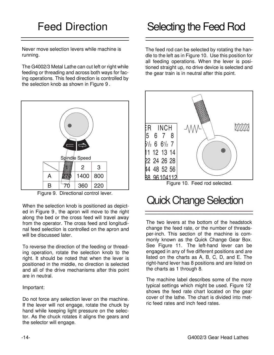
The feed rod can be selected by rotating the han- dle to the left as in Figure 10. Use this position for all feeding operations. When the lever is posi- tioned straight up, no drive device is selected and the gear train is in neutral after this point.
Figure 10. Feed rod selected.
Quick Change Selection
The two levers at the bottom of the headstock change the feed rate, or the number of threads-
The machine label describes some of the more typical settings which might be used. Figure 12 shows the feed rate chart located on the gear cover of the lathe. The chart is divided into met- ric feed rates and inch feed rates.
G4002/3 Gear Head Lathes |