NOTICE
The threading dial cannot be used when cut- ting metric threads. Once the half nut has been engaged, it must remain engaged throughout the threading process.
Half Nut Lever - This lever compresses and releases the half nut that engages the leadscrew. See Figure 16. The lever is only engaged while turning threads in stock. A lockout device fea- tured in the lever mechanism engages when the feed selector is used.
NOTICE
Do not simultaneously engage the feed lever and the threading lever. Doing so will damage the lathe.
![]()
![]() Dial
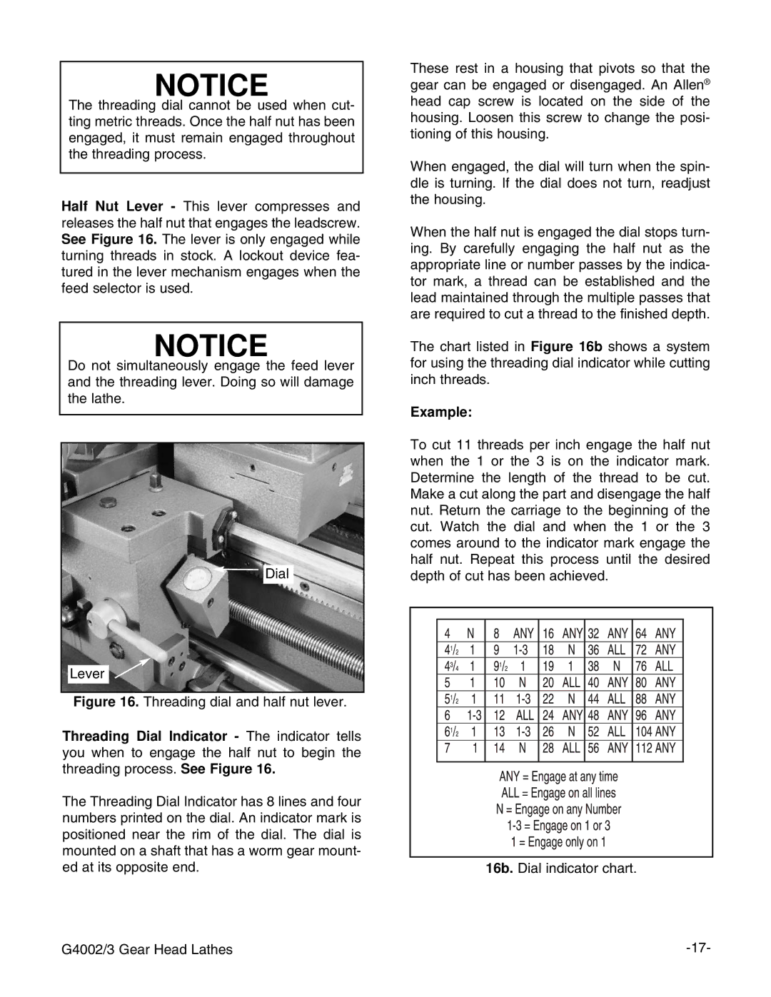
Dial
Lever ![]()
![]()
Figure 16. Threading dial and half nut lever.
Threading Dial Indicator - The indicator tells you when to engage the half nut to begin the threading process. See Figure 16.
The Threading Dial Indicator has 8 lines and four numbers printed on the dial. An indicator mark is positioned near the rim of the dial. The dial is mounted on a shaft that has a worm gear mount- ed at its opposite end.
These rest in a housing that pivots so that the gear can be engaged or disengaged. An Allen® head cap screw is located on the side of the housing. Loosen this screw to change the posi- tioning of this housing.
When engaged, the dial will turn when the spin- dle is turning. If the dial does not turn, readjust the housing.
When the half nut is engaged the dial stops turn- ing. By carefully engaging the half nut as the appropriate line or number passes by the indica- tor mark, a thread can be established and the lead maintained through the multiple passes that are required to cut a thread to the finished depth.
The chart listed in Figure 16b shows a system for using the threading dial indicator while cutting inch threads.
Example:
To cut 11 threads per inch engage the half nut when the 1 or the 3 is on the indicator mark. Determine the length of the thread to be cut. Make a cut along the part and disengage the half nut. Return the carriage to the beginning of the cut. Watch the dial and when the 1 or the 3 comes around to the indicator mark engage the half nut. Repeat this process until the desired depth of cut has been achieved.
16b. Dial indicator chart.
G4002/3 Gear Head Lathes |