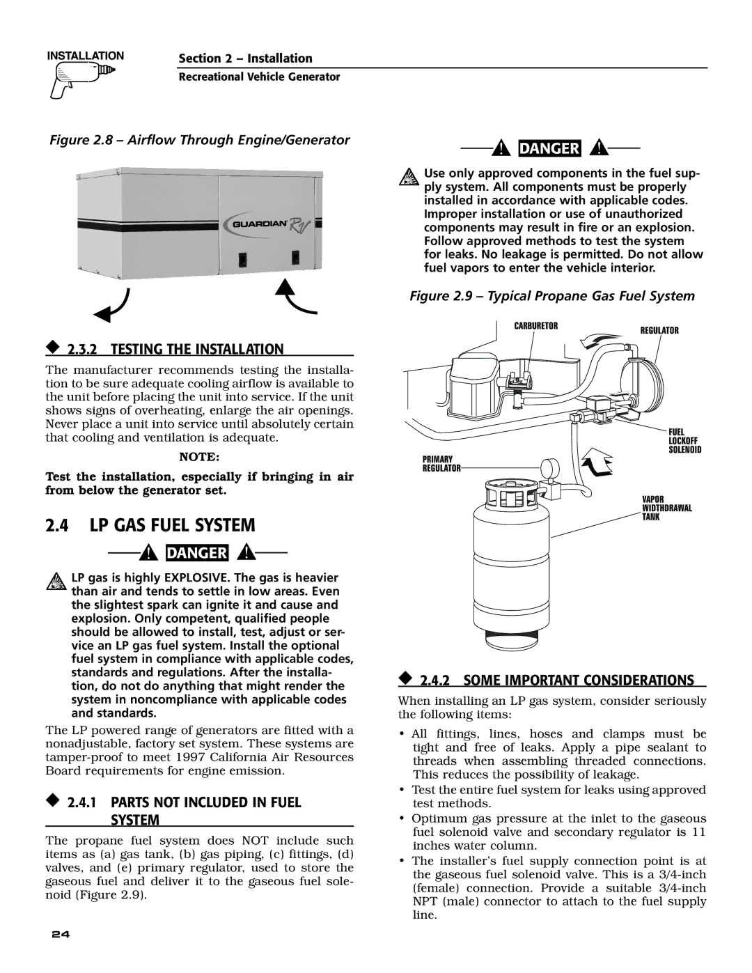
004701-0 specifications
Guardian Technologies 004701-0 is a state-of-the-art air purifier designed to enhance indoor air quality and create a healthier living environment. This innovative device utilizes advanced technologies to combat airborne pollutants, allergens, and other harmful particles, making it an excellent choice for homes, offices, and other indoor spaces.One of the standout features of the Guardian Technologies 004701-0 is its powerful True HEPA filtration system. True HEPA filters are capable of capturing 99.97% of particles as small as 0.3 microns, including dust, pollen, smoke, and pet dander. This ensures that the air you breathe is free from common allergens and irritants, promoting overall health and well-being.
In addition to its HEPA filter, the device incorporates a UV-C light technology that works to eliminate harmful bacteria and viruses. This dual-action air purification method not only filters out physical particles but also reduces the presence of microorganisms, further enhancing the air quality in your space. The UV-C light operates effectively without any chemicals, making it a safe and eco-friendly choice.
The Guardian Technologies 004701-0 is designed with user convenience in mind. It features a sleek, compact design that fits seamlessly into any room decor, and it operates quietly, ensuring that it does not disrupt your daily activities or sleep. The device also comes with multiple speed settings, allowing users to adjust the airflow based on their preferences and the size of the room.
Another notable characteristic of this air purifier is its filter replacement indicator. This feature alerts users when it’s time to replace the filter, ensuring that the unit operates at peak performance without any guesswork. The ease of maintenance makes it simple for users to keep the purifier running efficiently.
In conclusion, the Guardian Technologies 004701-0 is a powerful air purifier that combines advanced filtration and sanitization technologies to create a cleaner and healthier indoor environment. With its True HEPA filter, UV-C light, user-friendly design, and convenient features, it stands out as a reliable solution for improving indoor air quality and overall health. Whether you are looking to reduce allergens or simply breathe cleaner air, the Guardian Technologies 004701-0 is a wise investment for any household or workspace.

