Installation Procedure
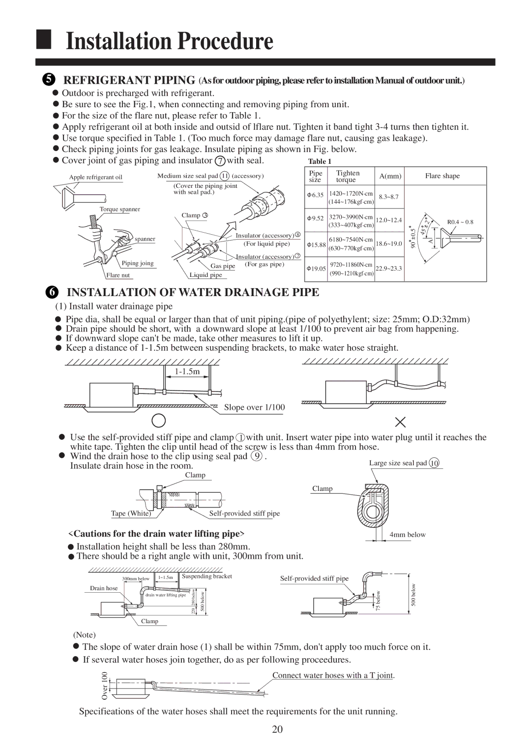
5. REFRIGERANT PIPING (As for outdoor piping, please refer to installation Manual of outdoor unit.)
![]() Outdoor is precharged with refrigerant.
Outdoor is precharged with refrigerant.
![]() Be sure to see the Fig.1, when connecting and removing piping from unit.
Be sure to see the Fig.1, when connecting and removing piping from unit.
![]() For the size of the flare nut, please refer to Table 1.
For the size of the flare nut, please refer to Table 1.
![]() Apply refrigerant oil at both inside and outsid of lflare nut. Tighten it band tight
Apply refrigerant oil at both inside and outsid of lflare nut. Tighten it band tight
![]() Use torque specified in Table 1. (Too much force may damage flare nut, causing gas leakage).
Use torque specified in Table 1. (Too much force may damage flare nut, causing gas leakage).
![]() Check piping joints for gas leakage. Insulate piping as shown in Fig. below.
Check piping joints for gas leakage. Insulate piping as shown in Fig. below. ![]() Cover joint of gas piping and insulator 7 with seal.
Cover joint of gas piping and insulator 7 with seal.
Apple refrigerant oil
Torque spanner
![]()
![]()
![]()
![]() spanner
spanner
Piping joing
Flare nut
Medium size seal pad 11 (accessory)
(Cover the piping joint with seal pad.)
Clamp 3
Insulator (accessory) 8 (For liquid pipe)
Insulator (accessory) 7 Gas pipe (For gas pipe)
Liquid pipe
Pipe | Tighten | A(mm) |
| Flare shape | |
size | torque |
| |||
|
|
|
| ||
6.35 | 1420~1720N.cm | 8.3~8.7 |
|
|
|
| (144~176kgf.cm) |
|
|
| |
9.52 | 3270~3990N.cm | 12.0~12.4 |
| 2 | R0.4 ~ 0.8 |
| (333~407kgf.cm) | 0.5 | |||
| 6180~7540N.cm |
| 45 | A | |
| 18.6~19.0 |
|
| ||
15.88 (630~770kgf.cm) | 90 |
| |||
19.05 | 9720~11860N.cm | 22.9~23.3 |
|
|
|
(990~1210kgf.cm) |
|
|
| ||
6. INSTALLATION OF WATER DRAINAGE PIPE
(1) Install water drainage pipe
![]() Pipe dia, shall be equal or larger than that of unit piping.(pipe of polyethylent; size: 25mm; O.D:32mm)
Pipe dia, shall be equal or larger than that of unit piping.(pipe of polyethylent; size: 25mm; O.D:32mm)
![]() Drain pipe should be short, with a downward slope at least 1/100 to prevent air bag from happening.
Drain pipe should be short, with a downward slope at least 1/100 to prevent air bag from happening.
![]() If downward slope can't be made, take other measures to lift it up.
If downward slope can't be made, take other measures to lift it up.
![]() Keep a distance of
Keep a distance of
Slope over 1/100
Use the
Wind the drain hose to the clip using seal pad 9 . Insulate drain hose in the room.
Clamp
Clamp
Tape (White)
<Cautions for the drain water lifting pipe>
![]() Installation height shall be less than 280mm.
Installation height shall be less than 280mm.
![]() There should be a right angle with unit, 300mm from unit.
There should be a right angle with unit, 300mm from unit.
Drain hose
300mm below 1~1.5m Suspending bracket | ||
280220below | 500below |
|
drain water lifting pipe |
|
|
Clamp |
|
|
![]() 75 below
75 below
(Note)
![]() The slope of water drain hose (1) shall be within 75mm, don't apply too much force on it.
The slope of water drain hose (1) shall be within 75mm, don't apply too much force on it. ![]() If several water hoses join together, do as per following proceedures.
If several water hoses join together, do as per following proceedures.
Over 100![]()
![]()
![]()
Connect water hoses with a T joint.
Specifieations of the water hoses shall meet the requirements for the unit running.
20