
 Installation procedure
Outdoor unit
Matters needing attention
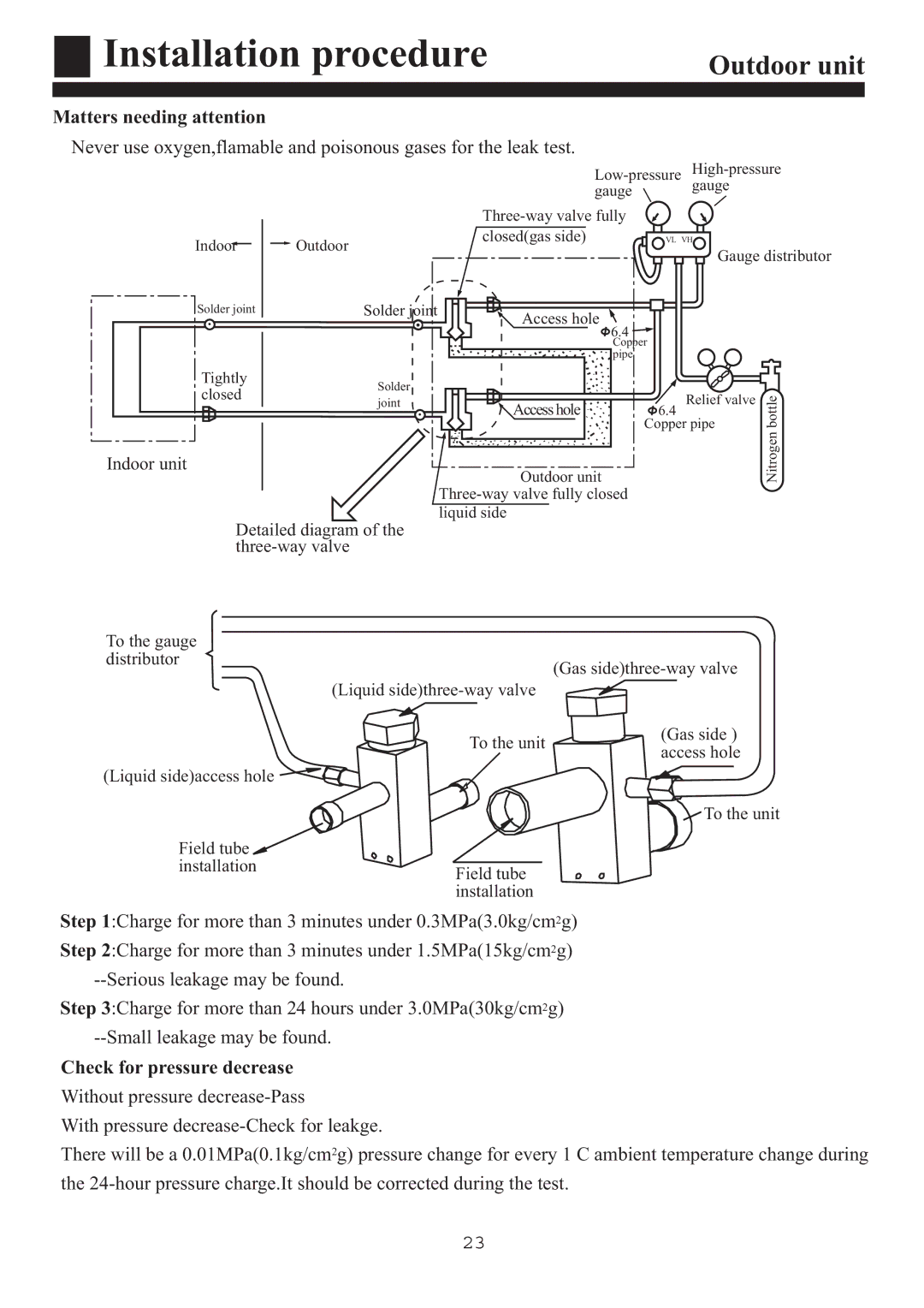
Never use oxygen,flamable and poisonous gases for the leak test.
gauge gauge
|
|
| ||
Indoor | Outdoor |
| closed(gas side) | VL VH |
|
| Gauge distributor | ||
|
|
|
| |
Solder joint |
| Solder joint | Access hole |
|
|
|
| 6.4 | |
|
|
|
| Copper |
pipe
Tightly | Solder |
| |
closed |
| ||
joint | Access hole | ||
| |||
|
|
6.4Relief valve
Copper pipe
bottle
Indoor unit
Outdoor unit
Nitrogen
Detailed diagram of the
To the gauge |
|
|
distributor |
| (Gas |
|
| |
| (Liquid |
|
| To the unit | (Gas side ) |
| access hole | |
|
| |
(Liquid side)access hole |
|
|
To the unit
Field tube |
|
installation | Field tube |
| |
| installation |
Step 1:Charge for more than 3 minutes under 0.3MPa(3.0kg/cm2g) Step 2:Charge for more than 3 minutes under 1.5MPa(15kg/cm2g)
Step 3:Charge for more than 24 hours under 3.0MPa(30kg/cm2g)
Check for pressure decrease Without pressure
With pressure
There will be a 0.01MPa(0.1kg/cm2g) pressure change for every 1 C ambient temperature change during the
23
