Electrical Diagram
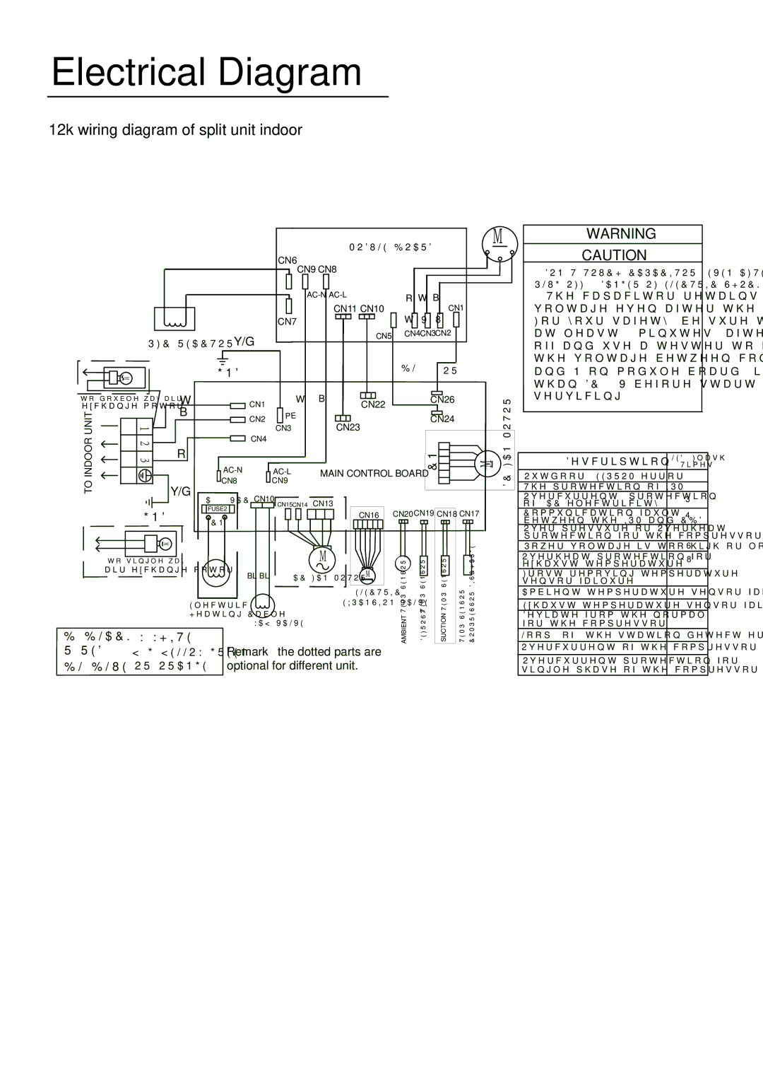
12k wiring diagram of split unit indoor
MODULE BOARD
|
|
| CN6CN9 CN8 |
|
|
|
|
|
|
|
|
|
| |||||||
|
|
|
|
|
|
|
|
|
|
|
|
| ||||||||
|
|
|
|
|
|
| R |
| W |
| B |
| ||||||||
|
|
|
|
|
|
|
|
|
| |||||||||||
|
|
|
|
|
|
|
|
|
| |||||||||||
|
|
|
|
|
| CN11 CN10 |
|
|
|
|
|
|
|
|
|
| ||||
|
|
|
|
|
|
|
|
|
|
|
|
|
|
|
| |||||
|
|
| CN7 |
|
|
|
|
| W |
| V |
| U | |||||||
|
|
|
|
| ||||||||||||||||
|
|
|
|
|
|
|
|
|
| |||||||||||
M
CN1
WARNING
CAUTION
DON'T TOUCH CAPACITOR, EVEN AFTER
The capacitor retains high voltage even after the
|
| PFC REACTOR | Y/G |
|
|
| CN5 | CN4CN3CN2 |
|
| ||
|
|
|
|
|
|
|
|
|
| |||
|
|
|
|
|
|
|
|
|
|
| ||
|
|
| GND |
|
|
|
| BL |
| OR |
|
|
| M |
|
|
|
|
|
|
|
|
| ||
|
|
|
|
|
|
|
|
|
|
|
| |
to | W | CN1 | W | B |
| CN22 |
|
| CN26 |
|
| |
exchange motor | B |
|
|
|
|
|
|
|
| |||
INDOORUNIT |
| CN2 | PE |
| CN23 |
|
| CN24 |
|
| ||
| 1 23 | CN3 |
|
|
|
|
| |||||
|
|
|
|
|
| M | MOTORFAN | |||||
| CN4 | MAIN CONTROL BOARD |
| |||||||||
|
|
|
|
|
|
|
|
|
|
|
| |
|
| R |
|
|
|
|
|
| CN21 |
|
| |
|
|
|
|
|
|
|
|
|
| |||
TO |
| Y/G | CN8 | CN9 |
|
|
|
|
|
|
| DC |
|
|
|
|
|
|
|
|
|
| |||
|
|
|
|
|
|
|
|
|
|
|
| |
|
| 1A/250VAC CN10 CN15CN14 | CN13 |
|
|
|
|
|
|
| ||
|
| GND | FUSE2 |
|
|
| CN16 CN20CN19 CN18 CN17 |
| ||||
|
| CN11 |
|
|
|
| ||||||
|
|
|
|
|
|
|
|
|
|
|
| |
|
| M |
|
|
|
|
|
|
|
|
|
|
to |
|
| M |
|
|
|
|
|
|
| ||
air exchange motor | BL BL |
|
|
| M |
|
|
|
|
| ||
|
|
| AC FAN MOTOR | AMBIENTTEMP.SENSOR | DEFROSTTEMP.SENSOR | SUCTIONTEMP.SENSOR |
|
| ||||
|
|
|
| TEMP.SENSOR DISCHARGECOMPRESSOR |
| |||||||
|
|
|
|
|
|
| ELECTRIC |
| ||||
|
| Electric |
|
|
| EXPANSION VALVE |
|
|
|
| ||
|
|
|
|
|
|
|
|
|
|
| ||
|
| Heating Cable |
|
|
|
|
|
|
|
|
| |
|
|
|
|
|
|
|
|
|
|
| ||
B:BLACK |
| W:WHITE |
|
|
|
|
|
|
|
|
|
|
R:RED | Y/G:YELLOW/GREEN Remark:the dotted parts are |
|
|
|
|
| ||||||
BL:BLUE | OR:ORANGE | optional for different unit. |
|
|
|
|
| |||||
at least 5 minutes. after plug off and use a tester to confirm the voltage between connector P and N(on module board) is less than DC 10V before start servicing.
|
| Description | LED1 Flash | |
|
|
| Times | |
Outdoor | EEPROM error |
| 1 | |
The protection of IPM |
| 2 | ||
Overcurrent protection |
| 3 | ||
of | AC electricity |
| ||
|
| |||
Communication fault |
| 4 | ||
between the IPM and CBD |
| |||
|
| |||
Over pressure or Overheat |
| 5 | ||
protection for the compressor |
| |||
|
| |||
Power voltage is too high or low |
| 6 | ||
Overheat protection for |
| 8 | ||
exhaust temperature |
| |||
|
| |||
| 10 | |||
sensor failure |
| |||
|
| |||
Ambient temperature sensor failure |
| 12 | ||
|
|
| ||
Exhaust temperature sensor failure |
| 13 | ||
Deviate from the normal |
| 18 | ||
for the compressor |
| |||
|
| |||
Loop | of | the station detect error |
| 19 |
|
|
| ||
Overcurrent of the compressor |
| 24 | ||
Overcurrent protection for |
| 25 | ||
| ||||
|
| |||
11