
0010515690, HW-09LN03, HW-12LN03 specifications
The Haier HW-12LN03, HW-09LN03, and model 0010515690 are part of Haier’s robust line-up of air conditioning units designed for efficient cooling and heating solutions. These models are particularly well-suited for residential and small office environments, providing comfort and energy savings through advanced technology.One of the standout features of the Haier HW-12LN03 and HW-09LN03 is their energy efficiency. Both models utilize the R410A refrigerant, which is known for its lower environmental impact and efficient heat transfer capabilities. This not only helps reduce electricity bills but also promotes eco-friendliness.
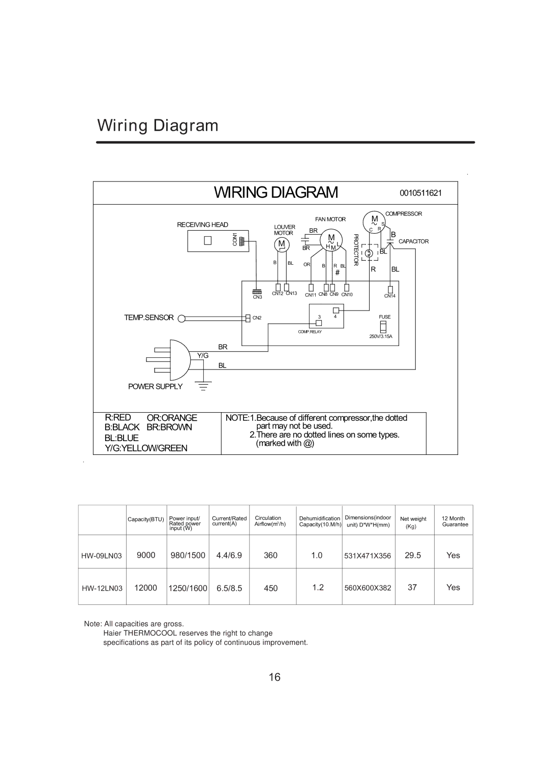
The cooling capacities of these units cater to different room sizes, with the HW-12LN03 offering a higher BTU rating suitable for larger spaces, while the HW-09LN03 is ideal for smaller areas. This versatility makes them suitable for a range of applications, from bedrooms to living rooms and offices.
In terms of technology, both models feature inverter technology which allows them to adjust their compressor speed based on the cooling demands of the space. This leads to more consistent temperatures, reduced energy consumption, and quieter operation. The inverter system provides significant energy savings compared to traditional non-inverter units, making them a smart choice for budget-conscious consumers.
Another appealing characteristic is the user-friendly remote control system that allows users to adjust settings from a distance. The intuitive interface and clear display make it easy to operate the air conditioning units, even for those less familiar with technology.
Moreover, these air conditioners come equipped with a multi-stage filtration system that helps improve indoor air quality by filtering out dust, allergens, and other pollutants. This is particularly beneficial for individuals with allergies or respiratory sensitivities.
Both the HW-12LN03 and HW-09LN03 models are designed with durability in mind, featuring robust outer casings and components that can withstand various environmental conditions. These qualities ensure that the units are reliable, with a long operational lifespan.
In summary, the Haier HW-12LN03, 0010515690, and HW-09LN03 represent an excellent choice for consumers looking for effective cooling and heating solutions. With their energy-efficient operation, advanced inverter technology, user-friendly features, and enhanced air quality improvements, these models stand out in the competitive air conditioning market.