Assembly
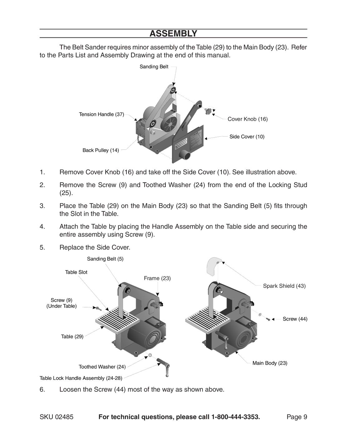
The Belt Sander requires minor assembly of the Table (29) to the Main Body (23). Refer to the Parts List and Assembly Drawing at the end of this manual.
Sanding Belt
Tension Handle (37)
TrackingCover Knob(16)
![]() Side Cover (10)
Side Cover (10)
Back Pulley (14)
1.Remove Cover Knob (16) and take off the Side Cover (10). See illustration above.
2.Remove the Screw (9) and Toothed Washer (24) from the end of the Locking Stud (25).
3.Place the Table (29) on the Main Body (23) so that the Sanding Belt (5) fits through the Slot in the Table.
4.Attach the Table by placing the Handle Assembly on the Table side and securing the entire assembly using Screw (9).
5.Replace the Side Cover.
Sanding Belt (5)
Table Slot
MainFrameBody(23)
Screw (9)
(Under Table)
Table (29) ![]()
Toothed Washer (24) ![]()
Table Lock Handle Assembly
6.Loosen the Screw (44) most of the way as shown above.
SparkCovShierld(43)(43)
![]()
![]()
![]()
![]()
![]() Screw (44)
Screw (44)
![]() Main Body (23)
Main Body (23)
SKU 02485 | For technical questions, please call | Page |