| To Install The Side Panels To The Stand: |
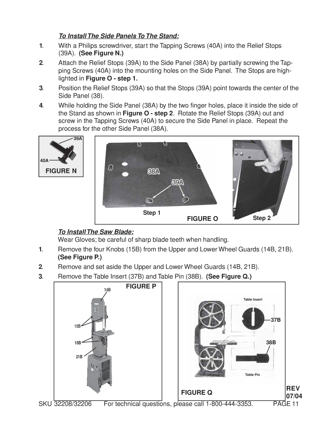
1. | With a Philips screwdriver, start the Tapping Screws (40A) into the Relief Stops |
| (39A). (See Figure N.) |
2. | Attach the Relief Stops (39A) to the Side Panel (38A) by partially screwing the Tap- |
| ping Screws (40A) into the mounting holes on the Side Panel. The Stops are high- |
| lighted in Figure O - step 1. |
3. | Position the Relief Stops (39A) so that the Stops (39A) point towards the center of the |
| Side Panel (38). |
4. | While holding the Side Panel (38A) by the two finger holes, place it inside the side of |
| the Stand as shown in Figure O - step 2. Rotate the Relief Stops (39A) out and |
| screw in the Tapping Screws (40A) to secure the Side Panel in place. Repeat the |
| process for the other Side Panel (38A). |
FIGURE N
|
| Step 1 | Step 2 | |||
|
|
|
| FIGURE O | ||
|
|
|
|
| ||
| To Install The Saw Blade: |
|
| |||
| Wear Gloves; be careful of sharp blade teeth when handling. |
|
| |||
1. | Remove the four Knobs (15B) from the Upper and Lower Wheel Guards (14B, 21B). | |||||
| (See Figure P.) |
|
| |||
2. | Remove and set aside the Upper and Lower Wheel Guards (14B, 21B). | |||||
3. | Remove the Table Insert (37B) and Table Pin (38B). (See Figure Q.) |
|
| |||
|
|
|
|
|
|
|
|
| FIGURE P |
|
| ||
37B
38B
FIGURE Q | REV | |
07/04 | ||
|
SKU 32208/32206 For technical questions, please call | PAGE 11 |
