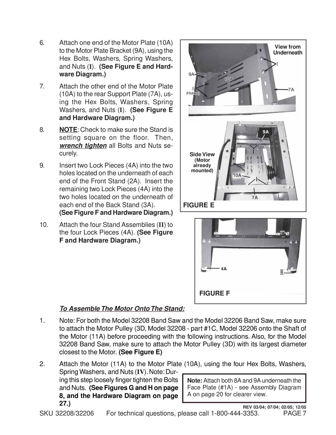
6.Attach one end of the Motor Plate (10A) to the Motor Plate Bracket (9A), using the
Hex Bolts, Washers, Spring Washers, and Nuts (I). (See Figure E and Hard- ware Diagram.)
7.Attach the other end of the Motor Plate (10A) to the rear Support Plate (7A), us-
ing the Hex Bolts, Washers, Spring Washers, and Nuts (I). (See Figure E and Hardware Diagram.)
8.NOTE: Check to make sure the Stand is setting square on the floor. Then, wrench tighten all Bolts and Nuts se- curely.
9.Insert two Lock Pieces (4A) into the two holes located on the underneath of each end of the Front Stand (2A). Insert the remaining two Lock Pieces (4A) into the two holes located on the underneath of each end of the Back Stand (3A).
(See Figure F and Hardware Diagram.)
10.Attach the four Stand Assemblies (II) to the four Lock Pieces (4A). (See Figure
F and Hardware Diagram.)
Side View
(Motor already mounted)
FIGURE E
View from
Underneath
FIGURE F
To Assemble The Motor Onto The Stand:
1.Note: For both the Model 32208 Band Saw and the Model 32206 Band Saw, make sure to attach the Motor Pulley (3D, Model 32208 - part #1C, Model 32206 onto the Shaft of the Motor (11A) before proceeding with the following instructions. Also, for the Model 32208 Band Saw, make sure to attach the Motor Pulley (3D) with its largest diameter closest to the Motor. (See Figure E)
2.Attach the Motor (11A) to the Motor Plate (10A), using the four Hex Bolts, Washers, Spring Washers, and Nuts (IV). Note: Dur-
ing this step loosely finger tighten the Bolts and Nuts. (See Figures G and H on page 8, and the Hardware Diagram on page 27.)
SKU 32208/32206 For technical questions, please call | PAGE 7 |