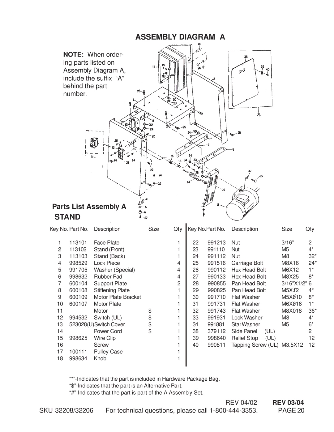
ASSEMBLY DIAGRAM A
NOTE: When order- ing parts listed on Assembly Diagram A, include the suffix “A” behind the part number.
Parts List Assembly A
STAND
Key No. Part No. | Description | Size | Qty | Key No.Part No. | Description |
| Size | Qty | ||
1 | 113101 | Face Plate |
| 1 | 22 | 991213 | Nut |
| 3/16” | 2 |
2 | 113102 | Stand (Front) |
| 1 | 23 | 991110 | Nut |
| M5 | 4* |
3 | 113103 | Stand (Back) |
| 1 | 24 | 991112 | Nut |
| M8 | 32* |
4 | 998529 | Lock Piece |
| 4 | 25 | 991516 | Carriage Bolt |
| M8X16 | 24* |
5 | 991705 | Washer (Special) |
| 4 | 26 | 990112 | Hex Head Bolt | M6X12 | 1* | |
6 | 998632 | Rubber Pad |
| 4 | 27 | 990133 | Hex Head Bolt | M8X25 | 8* | |
7 | 600104 | Support Plate |
| 2 | 28 | 990855 | Pan Head Bolt | 3/16”X1/2” 6 | ||
8 | 600108 | Stiffening Plate |
| 1 | 29 | 990825 | Pan Head Bolt | M5X12 | 4* | |
9 | 600109 | Motor Plate Bracket |
| 1 | 30 | 991710 | Flat Washer |
| M5X010 | 8* |
10 | 600107 | Motor Plate |
| 1 | 31 | 991731 | Flat Washer |
| M6X016 | 1* |
11 |
| Motor | $ | 1 | 32 | 991743 | Flat Washer |
| M8X018 | 36* |
12 | 994532 | Switch (UL) | $ | 1 | 33 | 991931 | Lock Washer |
| M8 | 4* |
13 | 523028(U)Switch Cover | $ | 1 | 34 | 991881 | Star Washer |
| M5 | 6* | |
14 |
| Power Cord | $ | 1 | 38 | 379112 | Side Panel | (UL) |
| 2 |
15 | 998625 | Wire Clip |
| 1 | 39 | 998640 | Relief Stop | (UL) |
| 12 |
16 |
| Screw |
| 1 | 40 | 990811 | Tapping Screw (UL) M3.5X12 | 12 | ||
17 | 100111 | Pulley Case |
| 1 |
|
|
|
|
|
|
18 | 998634 | Knob |
| 1 |
|
|
|
|
|
|
|
|
|
|
|
|
|
|
|
|
|
REV 04/02 | REV 03/04 |
SKU 32208/32206 For technical questions, please call | PAGE 20 |