UNPACKING
When unpacking, check to make sure all parts shown on the Parts List (pages 20, 22, 23, 24, 25 and 26) are included. If any parts are missing or broken, please call Harbor Freight Tools at the number shown on the cover of this manual as soon as possible.
OPERATING INSTRUCTIONS
NOTE: For additional references to the parts listed below, refer to pages 20, through 28 of this manual.
To Assemble The Stand:
1.NOTE: During the following 7 steps, loosely fin- ger tighten all Bolts and Nuts.
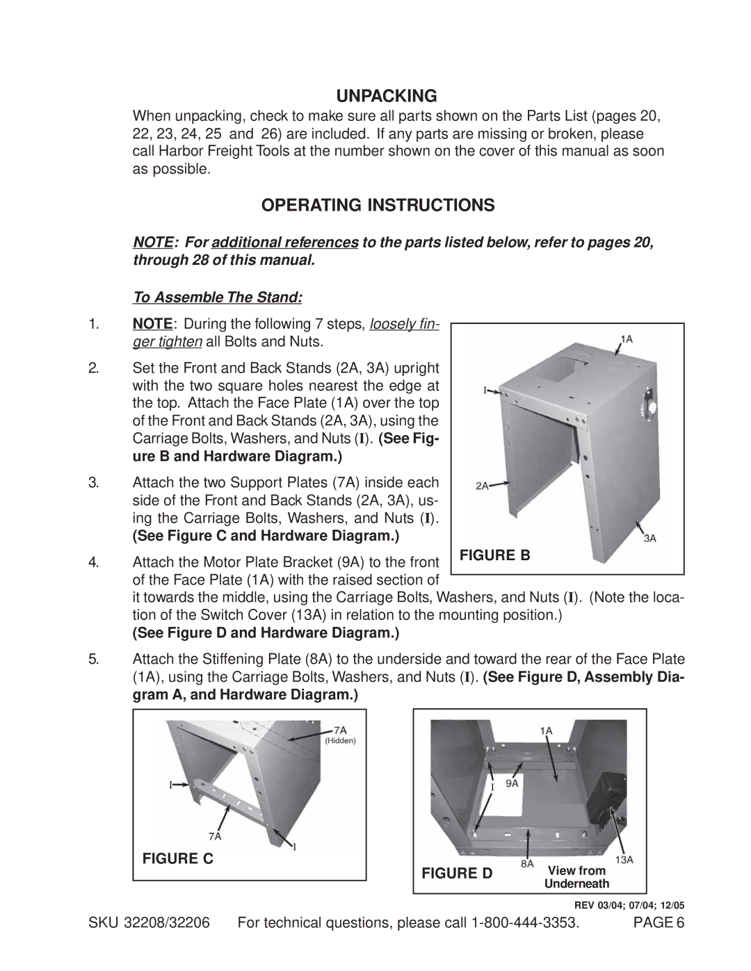
2.Set the Front and Back Stands (2A, 3A) upright with the two square holes nearest the edge at the top. Attach the Face Plate (1A) over the top
of the Front and Back Stands (2A, 3A), using the Carriage Bolts, Washers, and Nuts (I). (See Fig- ure B and Hardware Diagram.)
3.Attach the two Support Plates (7A) inside each
side of the Front and Back Stands (2A, 3A), us- ing the Carriage Bolts, Washers, and Nuts (I).
(See Figure C and Hardware Diagram.)
4. Attach the Motor Plate Bracket (9A) to the front of the Face Plate (1A) with the raised section of
it towards the middle, using the Carriage Bolts, Washers, and Nuts (I). (Note the loca- tion of the Switch Cover (13A) in relation to the mounting position.)
(See Figure D and Hardware Diagram.)
5.Attach the Stiffening Plate (8A) to the underside and toward the rear of the Face Plate (1A), using the Carriage Bolts, Washers, and Nuts (I). (See Figure D, Assembly Dia- gram A, and Hardware Diagram.)
FIGURE C
FIGURE D | View from | |
| Underneath |
|
| REV 03/04; 07/04; 12/05 | |
SKU 32208/32206 For technical questions, please call | PAGE 6 |