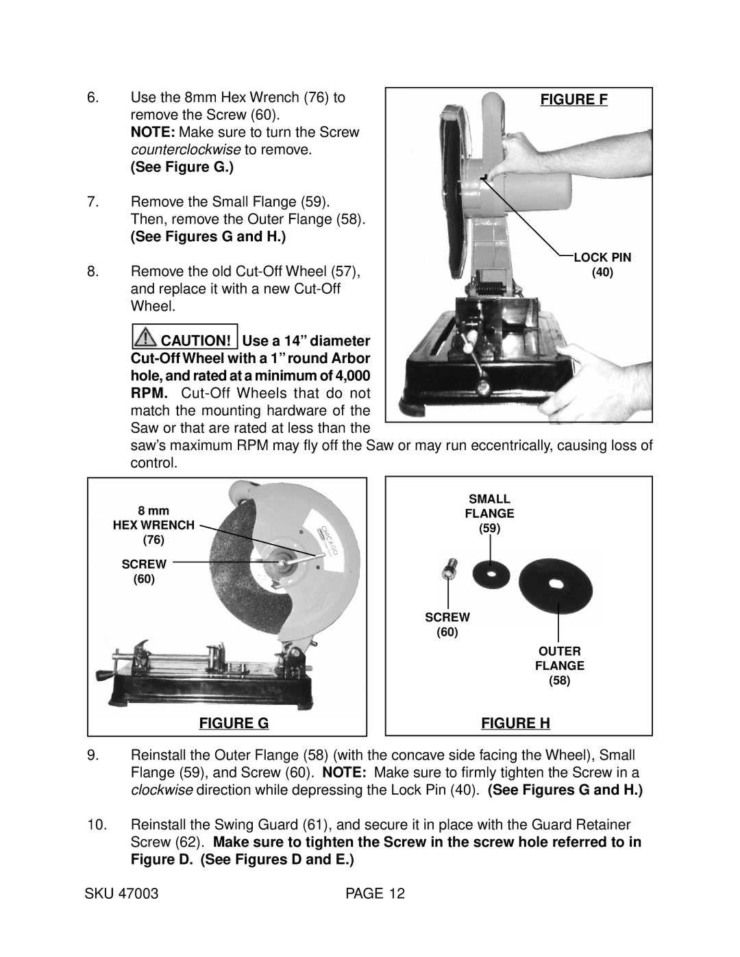
6. | Use the 8mm Hex Wrench (76) to | FIGURE F |
| remove the Screw (60). |
|
| NOTE: Make sure to turn the Screw |
|
| counterclockwise to remove. |
|
| (See Figure G.) |
|
7.Remove the Small Flange (59). Then, remove the Outer Flange (58).
(See Figures G and H.)
8. | Remove the old | LOCK PIN | ||
(40) | ||||
| and replace it with a new |
| ||
| Wheel. |
| ||
|
|
|
|
|
|
| CAUTION! | Use a 14” diameter |
|
|
|
| ||
| hole, and rated at a minimum of 4,000 |
| ||
| RPM. |
| ||
| match the mounting hardware of the |
| ||
| Saw or that are rated at less than the |
| ||
|
| |||
| saw’s maximum RPM may fly off the Saw or may run eccentrically, causing loss of | |||
| control. |
| ||
8mm
HEX WRENCH
(76)
SCREW
(60)
FIGURE G
SMALL
FLANGE
(59)
SCREW
(60)
OUTER
FLANGE
(58)
FIGURE H
9.Reinstall the Outer Flange (58) (with the concave side facing the Wheel), Small Flange (59), and Screw (60). NOTE: Make sure to firmly tighten the Screw in a clockwise direction while depressing the Lock Pin (40). (See Figures G and H.)
10.Reinstall the Swing Guard (61), and secure it in place with the Guard Retainer Screw (62). Make sure to tighten the Screw in the screw hole referred to in
Figure D. (See Figures D and E.)
SKU 47003 | PAGE 12 |
