PARTS LIST | PARTS LIST |
Part | Description | Q’ty |
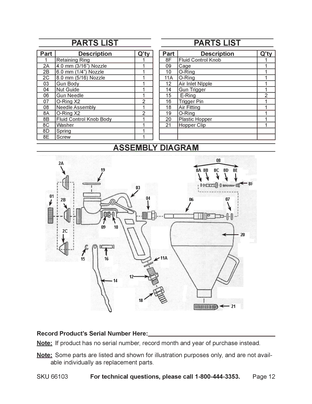
1 | Retaining Ring | 1 |
2A | 4.0 mm (3/16”) Nozzle | 1 |
2B | 6.0 mm (1/4”) Nozzle | 1 |
2C | 8.0 mm (5/16) Nozzle | 1 |
03 | Gun Body | 1 |
04 | Nut Guide | 1 |
06 | Gun Needle | 1 |
07 | 2 | |
08 | Needle Assembly | 1 |
8A | 2 | |
8B | Fluid Control Knob Body | 1 |
8C | Washer | 1 |
8D | Spring | 1 |
8E | Screw | 1 |
Part | Description | Q’ty |
8F | Fluid Control Knob | 1 |
09 | Cage | 1 |
10 | 1 | |
11A | 1 | |
12 | Air Inlet NIpple | 1 |
14 | Gun Trigger | 1 |
15 | 2 | |
16 | Trigger Pin | 1 |
18 | Air Fitting | 1 |
19 | 1 | |
20 | Plastic Hopper | 1 |
21 | Hopper Clip | 1 |
Assembly Diagram
Record Product’s Serial Number Here:
Note: If product has no serial number, record month and year of purchase instead.
Note: Some parts are listed and shown for illustration purposes only, and are not avail- able individually as replacement parts.
SKU 66103 | For technical questions, please call | Page 12 |