SPEED CONTROL
LEVER
FIGURE J
FIGURE K SPEED LABEL (49)
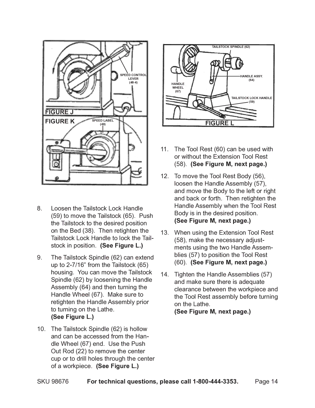
8.Loosen the Tailstock Lock Handle (59) to move the Tailstock (65). Push the Tailstock to the desired position on the Bed (38). Then retighten the Tailstock Lock Handle to lock the Tail- stock in position. (See Figure L.)
9.The Tailstock Spindle (62) can extend up to
(See Figure L.)
TAILSTOCK SPINDLE (62)
HANDLE ASSY.
(64)
HANDLE
WHEEL
(67)
TAILSTOCK LOCK HANDLE
(59)
FIGURE L
11.The Tool Rest (60) can be used with or without the Extension Tool Rest (58). (See Figure M, next page.)
12.To move the Tool Rest Body (56), loosen the Handle Assembly (57), and move the Body to the left or right and back or forth. Then retighten the Handle Assembly when the Tool Rest Body is in the desired position.
(See Figure M, next page.)
13.When using the Extension Tool Rest (58), make the necessary adjust- ments using the two Handle Assem- blies (57) to position the Tool Rest (60). (See Figure M, next page.)
14.Tighten the Handle Assemblies (57) and make sure there is adequate clearance between the workpiece and the Tool Rest assembly before turning on the Lathe.
(See Figure M, next page.)
10.The Tailstock Spindle (62) is hollow and can be accessed from the Han- dle Wheel (67) end. Use the Push Out Rod (22) to remove the center cup or to drill holes through the center of a workpiece. (See Figure L.)
SKU 98676 | For technical questions, please call | Page 14 |